
Sheet post-processing apparatus and image forming apparatus

a post-processing apparatus and image forming technology, applied in the direction of electrographic process, instruments, transportation and packaging, etc., can solve the problems of inability to reliably bound, increased load on the staple, and inability to meet the needs of staples, etc., to achieve the effect of not increasing the size of the apparatus, noise, vibration, or power consumption

Inactive Publication Date: 2005-07-14
NISCA KK
View PDF0 Cites 17 Cited by
  • Summary
  • Abstract
  • Description
  • Claims
  • Application Information

AI Technical Summary

Benefits of technology

[0013] In the first aspect of the present invention, the binding device uses the staples to bind the sheet bundle at the punched positions on the sheets punched by the punching device as the bound positions. Thus, the binding device does not need to drive the staples all the sheets constituting the sheet bundle. Consequently, the binding device can bind the sheet bundle without increasing a size of the apparatus, noise, vibration, or power consumption. Further, the sheets not subjected to the punching process are stapled to fix positions of the staples. Therefore, leg portions of the staples can be appropriately bent, thereby properly binding the sheet bundle.
[0014] In the first aspect, the punching device may avoid punching the sheet bundle at the bound position on at least the last sheet penetrated by the leg portions of the staples driven by the binding device into the sheet bundle. The last sheet is included in the sheets constituting the sheet bundle formed by the sheet bundle forming device. After the binding process, the staples move within the punching positions of the sheets of the sheet bundle to prevent the sheets from coming off sequentially or all together from between the bent leg portions of the staples and then loosening.
[0015] Alternatively, the punching device may avoid punching the sheet bundle at the bound position on at least the first sheet penetrated by the leg portions of the staples driven by the binding device into the sheet bundle. The first sheet is included in the sheets constituting the sheet bundle formed by the sheet bundle forming device. When the first sheet penetrated by the leg portions of the staples becomes a front surface of the sheet bundle, a punching mark on the sheets is hidden, making the sheet bundle look good.
[0024] According to the present invention, the binding device uses staples to bind the sheet bundle at the punched positions on the sheets punched by the punching device as the bound positions. The sheets are included in the sheet bundle formed by the sheet bundle forming device. Accordingly, the binding device does not need to drive the staples all the sheets constituting the sheet bundle. This allows the binding device to bind the sheet bundle without increasing a size of the apparatus, noise, vibration, or power consumption. Further, the sheets not subjected to the punching process are stapled to fix the positions of the staples. Therefore, the leg portions of the staples can be appropriately bent, and the sheet bundle is reliably bound.

Problems solved by technology

Accordingly, when the sheet bundle has a large thickness, leg portions (tip portions) of a staple may not withstand the load and may be bent, thereby causing inappropriate binding.
Accordingly, for a certain type of sheets, the load on the staple becomes greater, thereby causing a problem similar to that associated with a large number of sheets.
However, in this case, a driving force greater the load is required to drive the staple into the sheet bundle.
Noise or vibration also increases when the staple is penetrated into the sheet bundle, and power consumption increases.
When a bundle of sheets is bound with a strong staple, it is difficult to remove the staple, thereby making it difficult to handle the sheet post-processing apparatus.

Method used


Image

  • Sheet post-processing apparatus and image forming apparatus
  • Sheet post-processing apparatus and image forming apparatus
  • Sheet post-processing apparatus and image forming apparatus

Examples


Embodiment Construction

[0033] Hereunder, embodiments of the present invention will be described with reference to the accompanying drawings.

(Configuration)

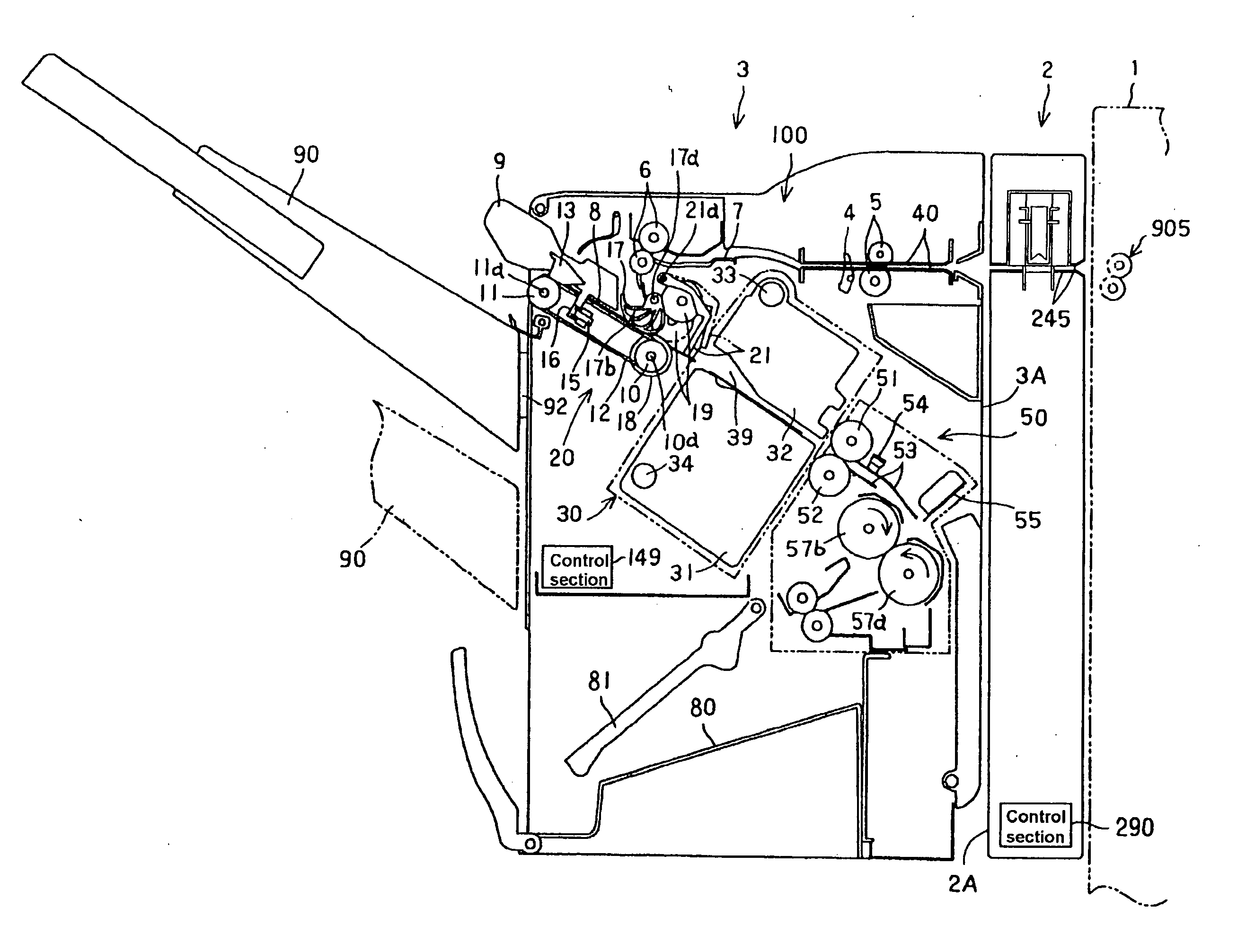
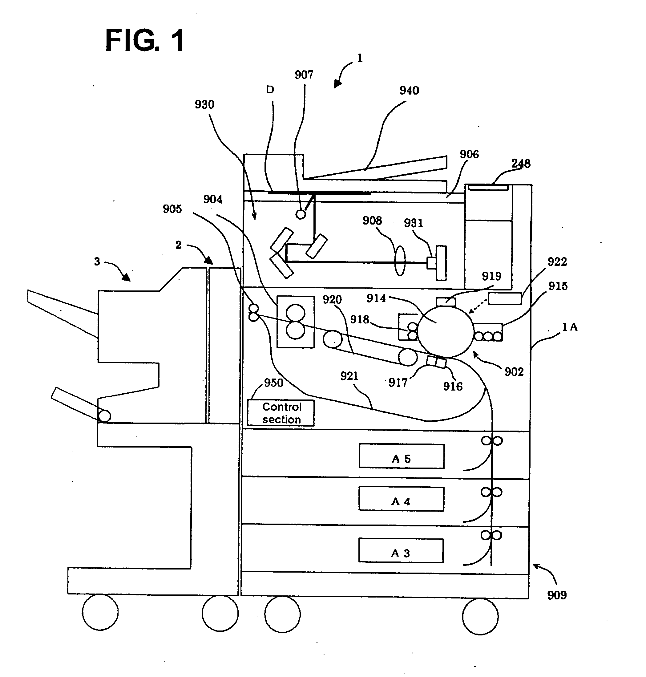
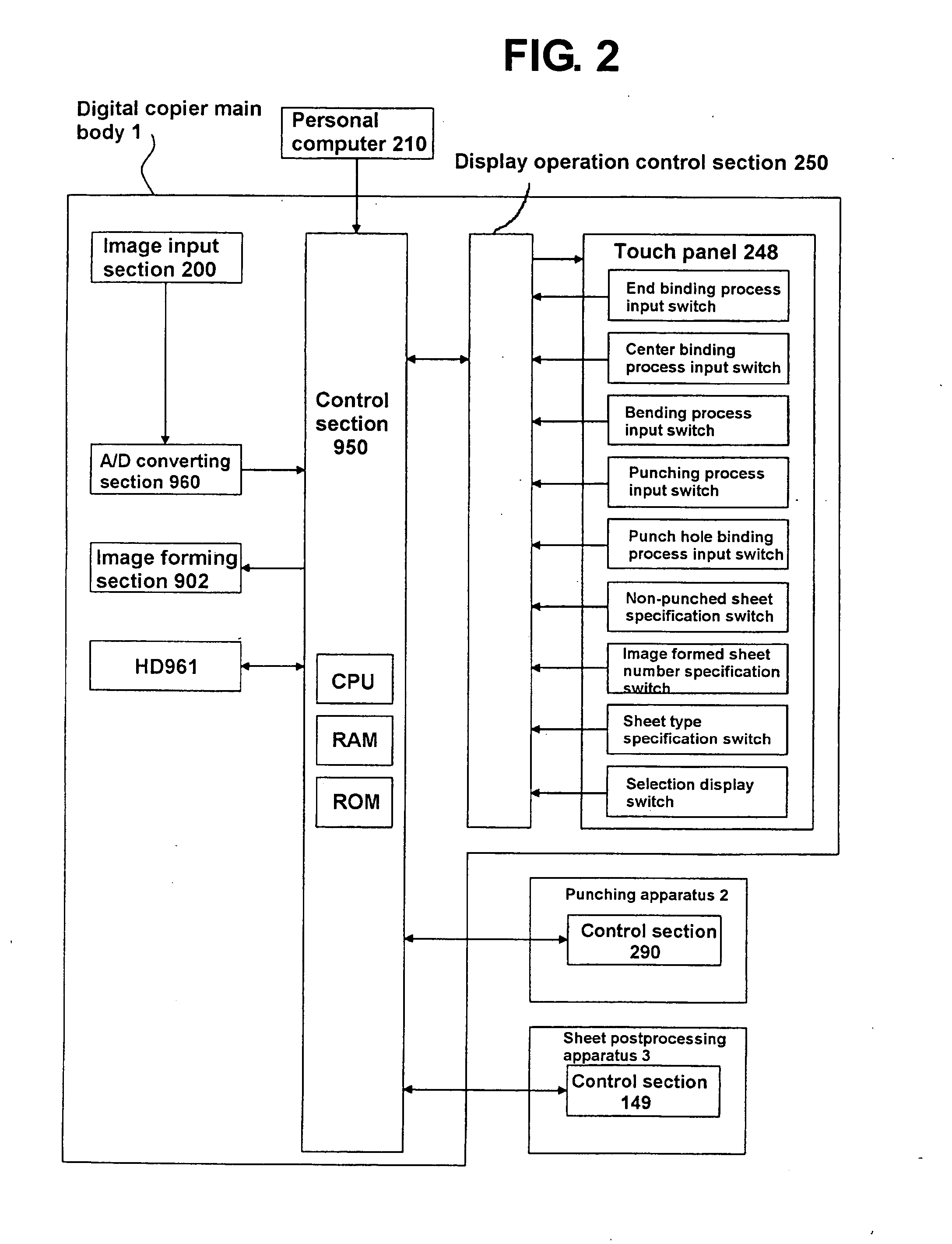
[0034] As shown in FIG. 1, according to an embodiment, a digital copier 1 comprises a digital copier main body 1A that forms images on sheets, a sheet punching apparatus 2 installed on a side of the digital copier main body 1A to punch the sheets with the images conveyed by the digital copier main body 1A, and a sheet post-processing apparatus 3 installed on a downstream side of the sheet punching apparatus 2 to execute a binding process or the like on a sheet bundle composed of the plurality of sheets. In the present embodiment, the sheet punching apparatus 2 is one of option apparatus of the sheet post-processing apparatus 3. In the present invention, the sheet punching apparatus 2 functions as a part of a sheet post-processing apparatus.

[0035] The digital copier main body 1A has an image forming section 902 as an image forming device for recordin...


PUM

PropertyMeasurementUnit
poweraaaaaaaaaa
thicknessaaaaaaaaaa
strengthaaaaaaaaaa

Abstract

A sheet post-processing apparatus includes a loading section for loading a sheet, and a punching device for punching the sheet loaded in the loading section at a punching position. A sheet bundle forming device is provided for forming a sheet bundle of the sheet punched by the punching device and a sheet not punched by the punching device. A binding device drives a staple into the sheet bundle at the punching position as a bound position to bind the sheet bundle.

Description

BACKGROUND OF THE INVENTION AND RELATED ART STATEMENT [0001] The present invention relates to a sheet post-processing apparatus and an image forming apparatus, and in particular, to a sheet post-processing apparatus and an image forming apparatus for forming and binding a bundle of sheets with images. [0002] A sheet post-processing apparatus has been known for aligning ends of a plurality of sheets and forming the sheets into a bundle. The sheets are discharged from an image forming apparatus such as a printer or a facsimile machine after images are printed on the sheets. The sheet post-processing apparatus uses a stapler to staple and bind the sheet bundle (see, for example, Patent Document 1). Such a sheet post-processing apparatus discharges a bundle of sheets with the ends thereof aligned with one another after being bound. Consequently, the finished sheet bundle appears neat, and it is not necessary to manually align and bind the sheets discharged by the image forming apparatus...

Claims


Application Information

Patent Timeline
Patent Type & Authority Applications(United States)
IPC IPC(8): B26F1/04B42B5/08B42C1/12B65H37/04G03G15/00
CPCB26F1/04B42B5/08B42C1/12B65H2301/5152B65H2511/40B65H2513/51G03G15/6582G03G2215/00822G03G2215/00818B65H2220/01B65H2220/02
Inventor MOCHIZUKI, NAOTO
Owner NISCA KK
Learn More