Compressor
- Summary
- Abstract
- Description
- Claims
- Application Information
AI Technical Summary
Benefits of technology
Problems solved by technology
Method used
Image
Examples
first embodiment
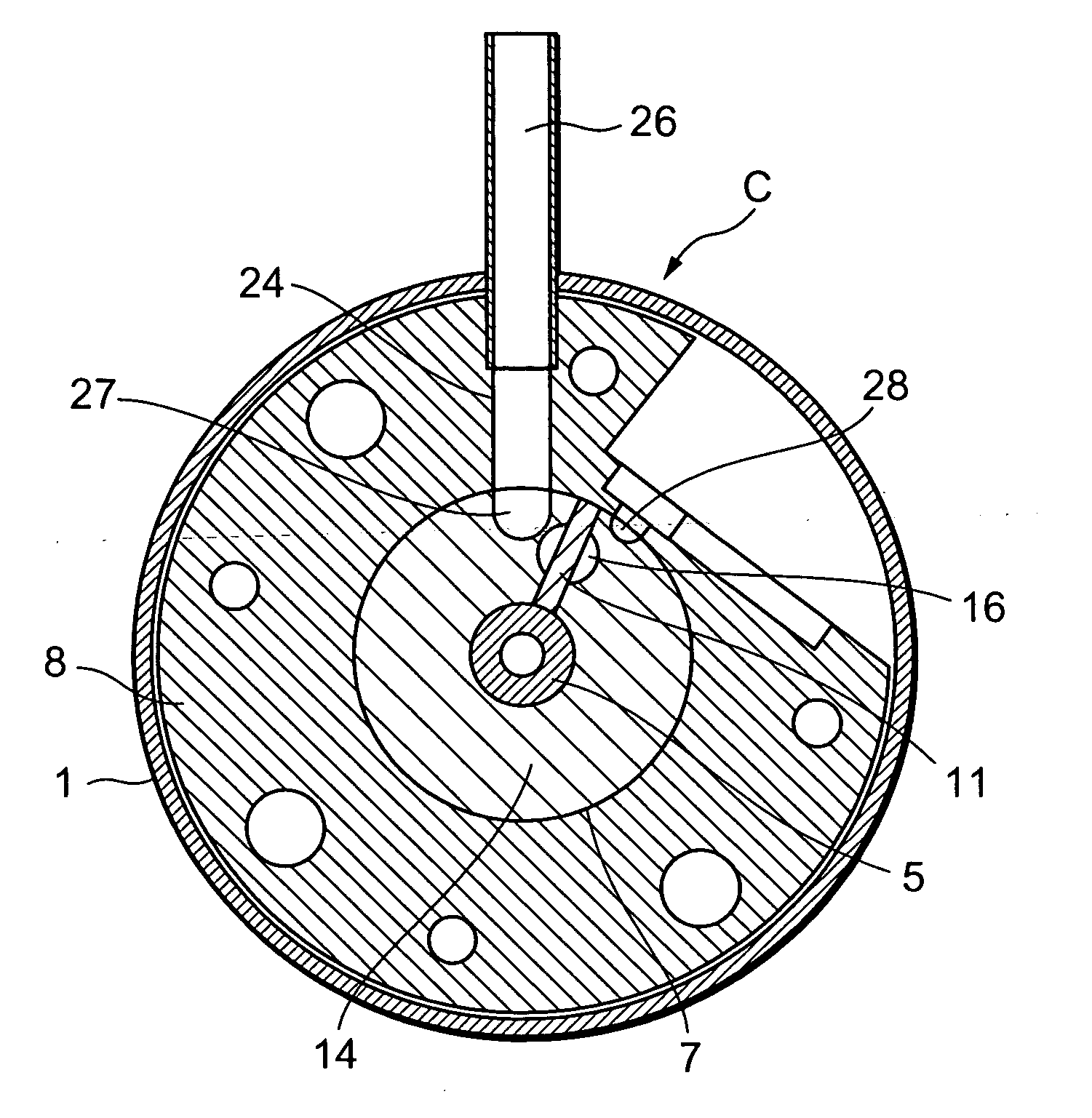
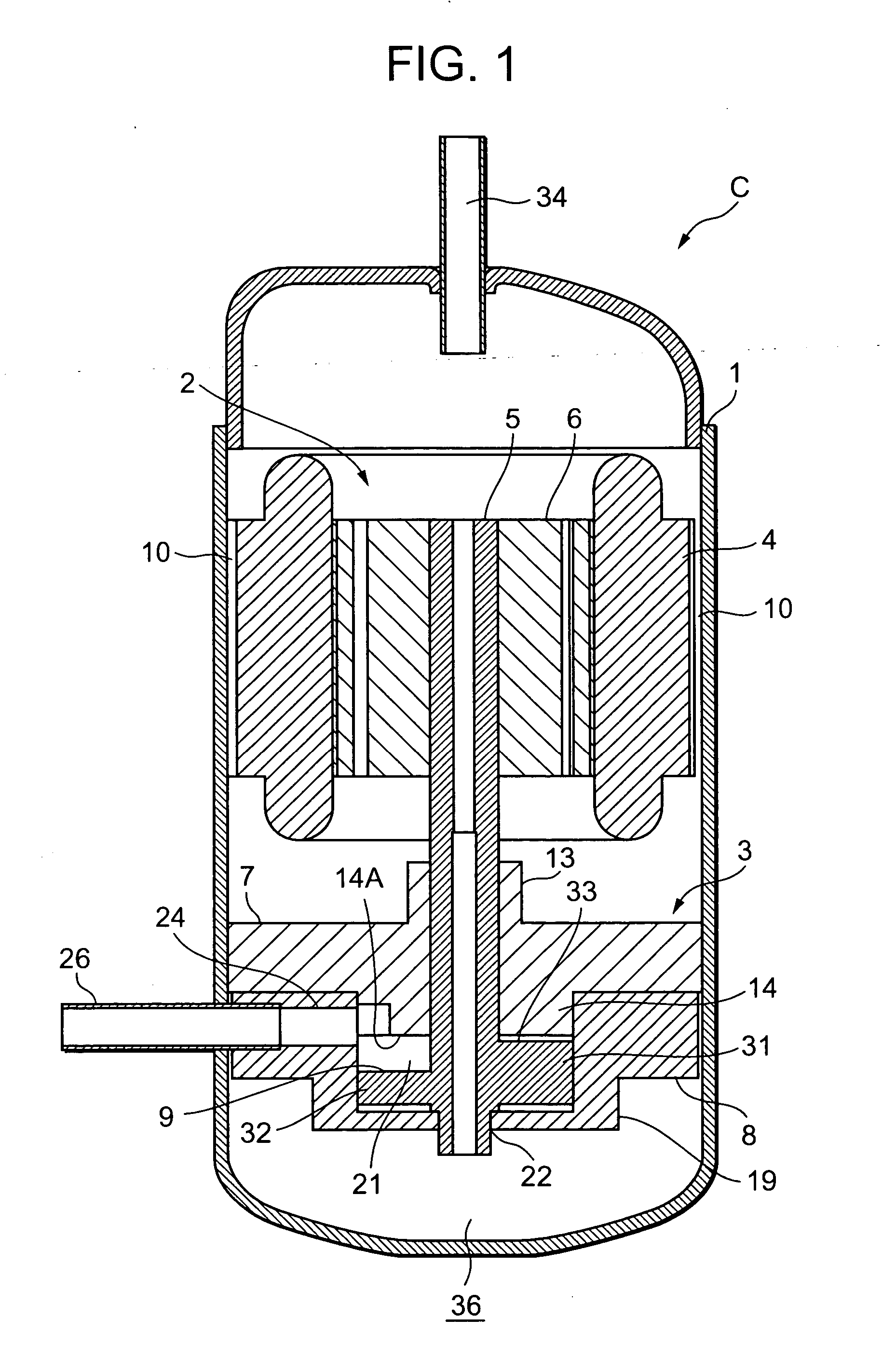
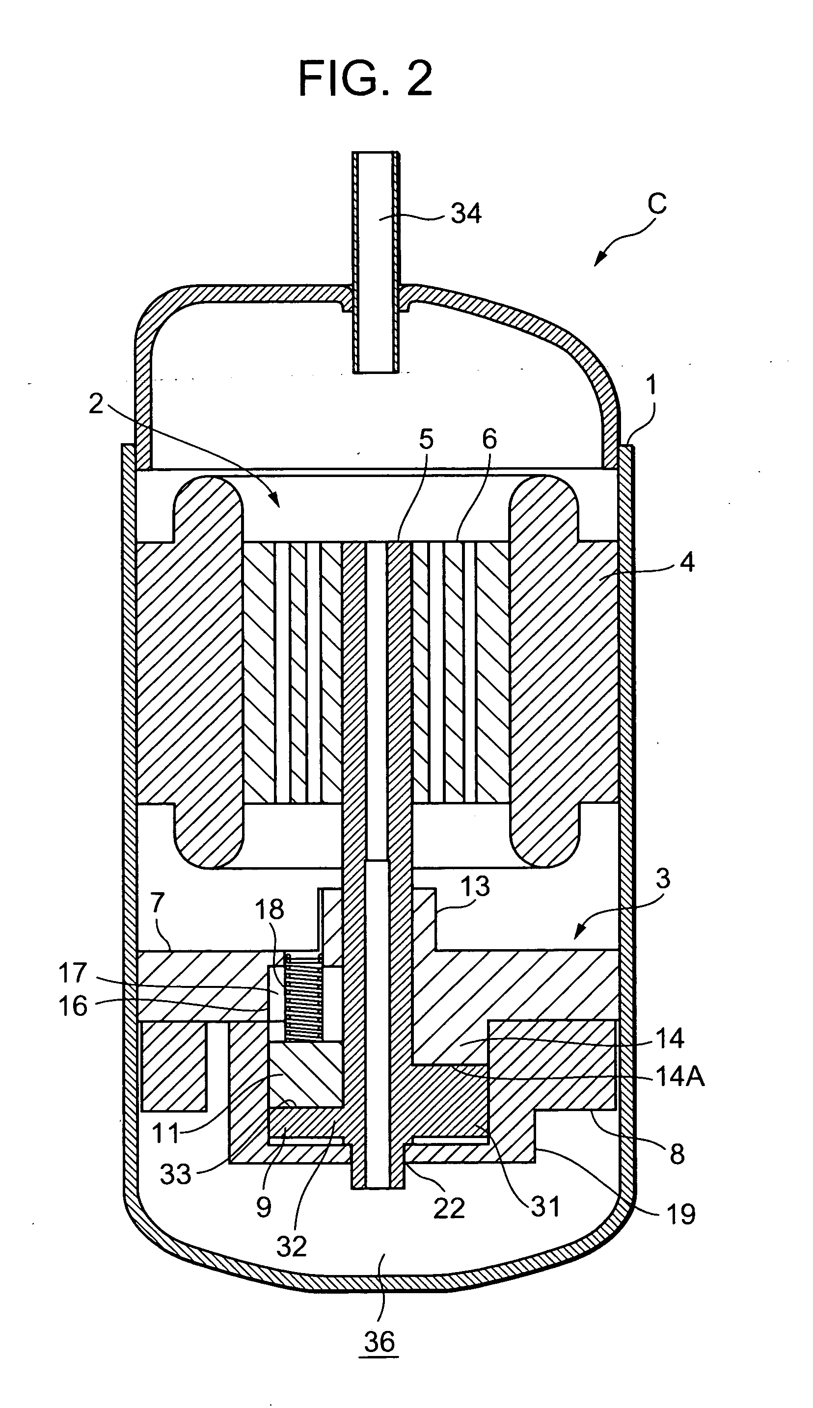
[0083]FIG. 1 is a vertical sectional side view showing the compressor C according to a first embodiment of the present invention, FIG. 2 is another vertical sectional side view, FIG. 3 is a plan sectional view of the compressor C, FIG. 4 is another plan sectional view, FIGS. 5 to 7 are perspective views of a compression element 3 of the compressor C, and FIGS. 8, 9 are side views thereof. Throughout the drawings, a reference numeral 1 denotes a sealed container which receives a driving element 2 in its upper side and a compression element 3 driven by the driving element 2 in its lower side.
[0084] The driving element 2 is an electric motor which is fixed to an inner wall of the sealed container 1 and which comprises a stator 4 having a stator coil wound thereon and a rotor 6 having a rotary shaft 5 in a center inside the stator 4. Incidentally, a clearance 10 is formed between an outer peripheral part of the stator 4 of the driving element 2 and the sealed container 1 to communicate...
second embodiment
[0099] Next, referring to FIGS. 14 to 24, the compressor C of a second embodiment will be described. FIG. 14 is a vertical sectional side view of the compressor C of the second embodiment, FIG. 15 is another vertical sectional side view, FIGS. 16 to 18 are perspective views of a compression element 3 of the compressor C in this case, FIGS. 19, 20 are side views thereof, FIGS. 21 and 22 are side views of a rotary shaft 5 which includes a compression member 9, FIG. 23 is a bottom view, and FIG. 24 is a perspective view.
[0100] Throughout the drawings, portions denoted by reference numerals similar to those of FIGS. 1 to 13 exhibit identical or similar functions, and thus description thereof will be omitted. In this case, a recess 39 is formed from a bottom surface (other surface) 38 in a portion corresponding to a thick part 31 of the compression member 9. A depth of the recess 39 is formed along a slope of an upper surface 33, and a position corresponding to a top dead center 33A is ...
third embodiment
[0102] Next, referring to FIGS. 25 to 35, the compressor C of a third embodiment will be described. FIG. 25 is a vertical sectional side view of the compressor C of the second embodiment, FIG. 26 is another vertical sectional side view, FIGS. 27 to 29 are perspective views of a compression element 3 of the compressor C in this case, FIGS. 30, 31 are side views thereof, FIGS. 32 and 33 are side views of a rotary shaft 5 which includes a compression member 9 in this case, FIG. 34 is a bottom view, and FIG. 35 is a perspective view.
[0103] Throughout the drawings, portions denoted by reference numerals similar to those of FIGS. 1 to 24 exhibit identical or similar functions, and thus description thereof will be omitted. A bottom surface (other surface) 38 of the compression member 9 is formed to be a slope directed from the rotary shaft 5 side to a peripheral part in which the peripheral part side rises to approach an upper surface 33 side. Thus, since air resistance during rotation of...
PUM
 Abstract
Description
Claims
Application Information
 - R&D
- Intellectual Property
- Life Sciences
- Materials
- Tech Scout
- Unparalleled Data Quality
- Higher Quality Content
- 60% Fewer Hallucinations
Browse by: Latest US Patents, China's latest patents, Technical Efficacy Thesaurus, Application Domain, Technology Topic, Popular Technical Reports.
© 2025 PatSnap. All rights reserved.Legal|Privacy policy|Modern Slavery Act Transparency Statement|Sitemap|About US| Contact US: help@patsnap.com


