Electrical connection device to make a metallisation point, support equipped with such a connection device and aircraft equipped with such a support

a technology of electric connection and metallisation point, which is applied in the direction of connection contact material, coupling device connection, aircraft static discharger, etc., can solve the problems of high application cost, long time and varnish application time, and first preparation of protective varnish

Inactive Publication Date: 2005-07-14
AIRBUS OPERATIONS (SAS)
View PDF9 Cites 39 Cited by
  • Summary
  • Abstract
  • Description
  • Claims
  • Application Information

AI Technical Summary

Benefits of technology

[0047] One advantage of the connection device according to the invention lies in the fact that (i) the electrical contact is made between each stripped contact area on the conducting face(s) of the support and the corresponding contact part, that is electrically conducting, (ii) each contact area is kept air t...

Problems solved by technology

A first disadvantage lies in the fact that the protective varnish must firstly be prepared before being applied, using a brush.
The preparation time and the varnish application time are relatively long, which induces high application costs.
A second disadvantage lies in the fact that the protective varnish is usually insulating, which makes checks on the electrical connection difficult after the varnish has been applied.
A third disadvantage lies in the fact that the varnish can scale with time, which modifies ...

Method used


Image

  • Electrical connection device to make a metallisation point, support equipped with such a connection device and aircraft equipped with such a support
  • Electrical connection device to make a metallisation point, support equipped with such a connection device and aircraft equipped with such a support
  • Electrical connection device to make a metallisation point, support equipped with such a connection device and aircraft equipped with such a support

Examples


first embodiment

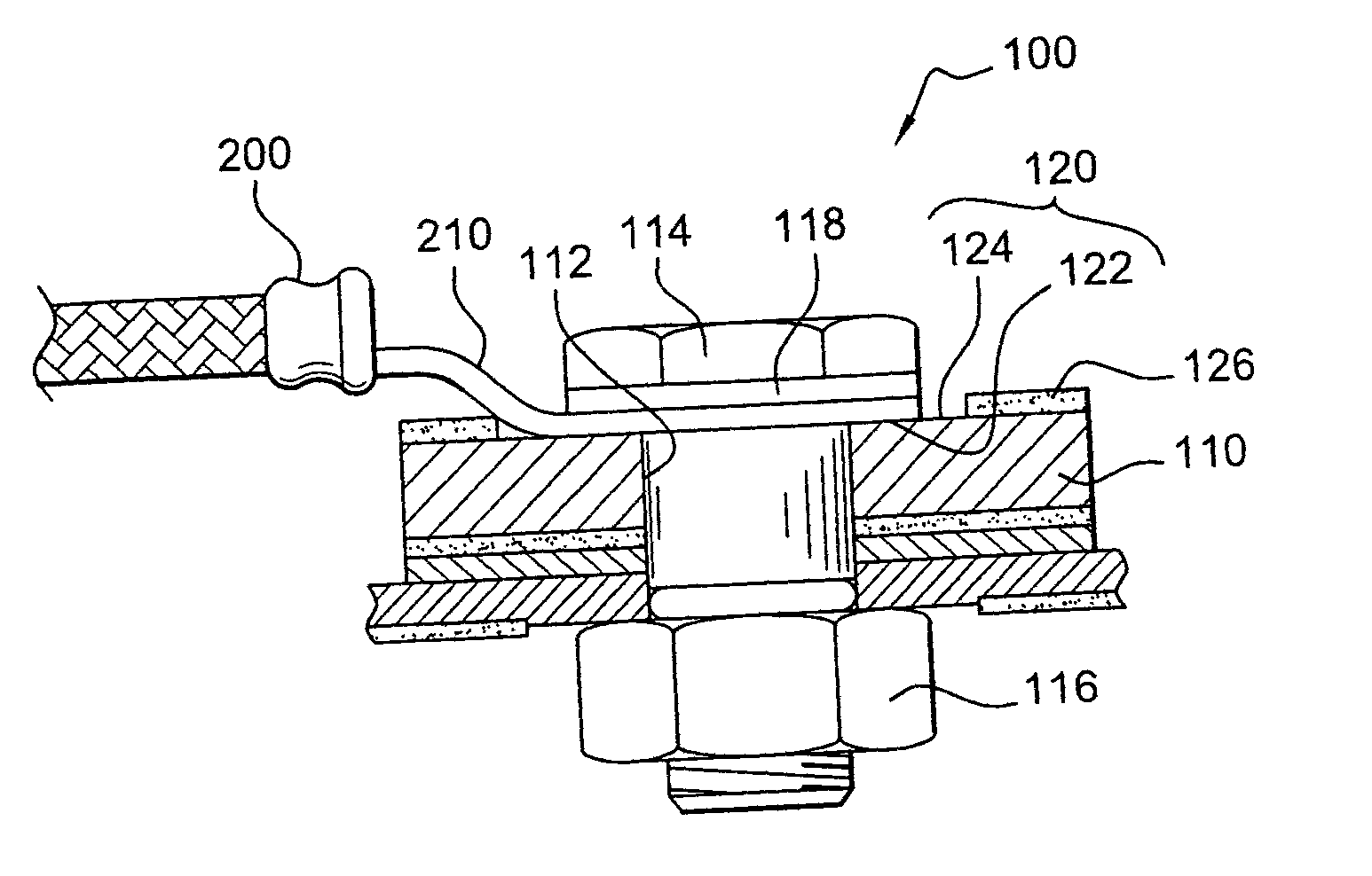
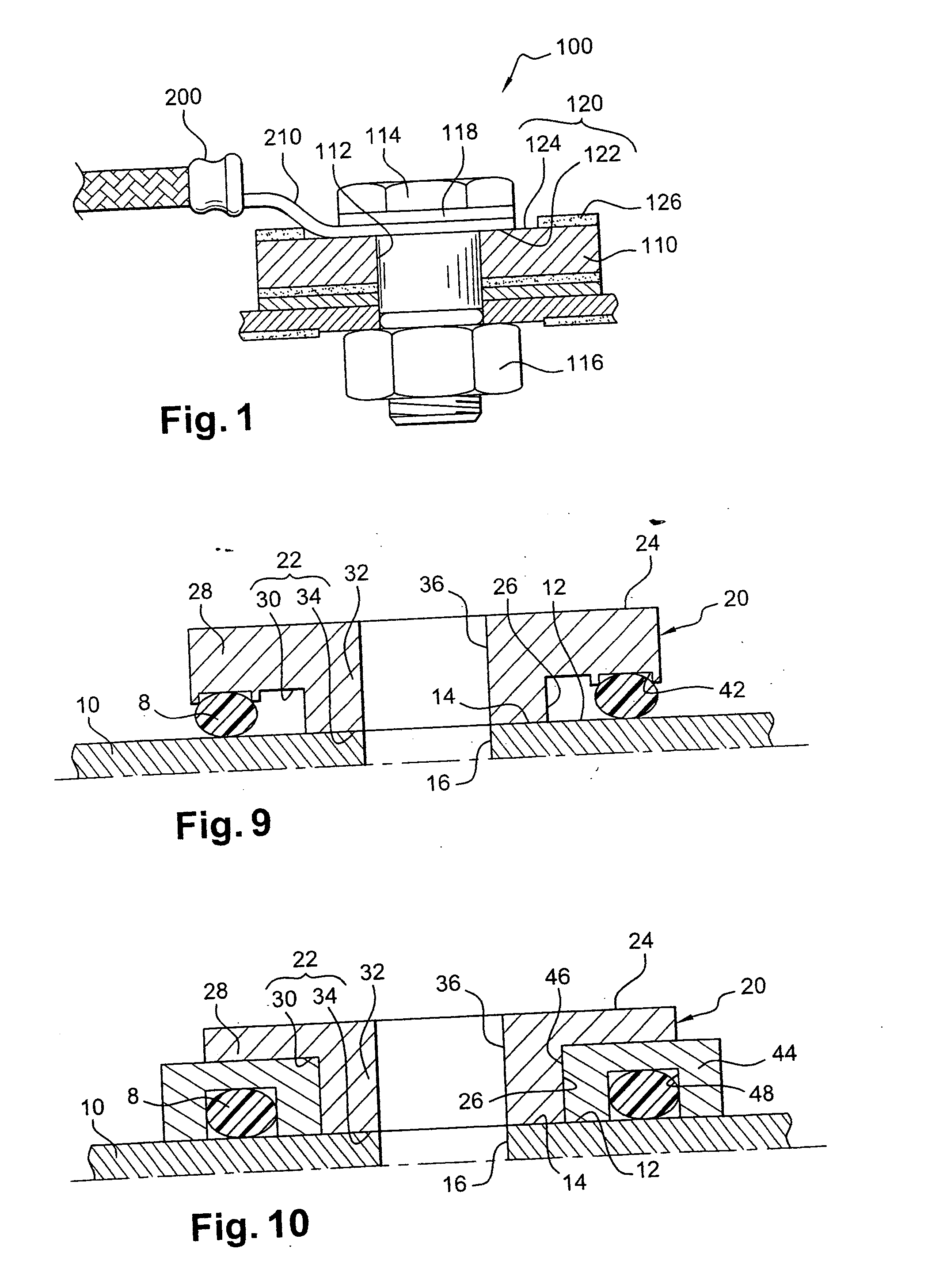
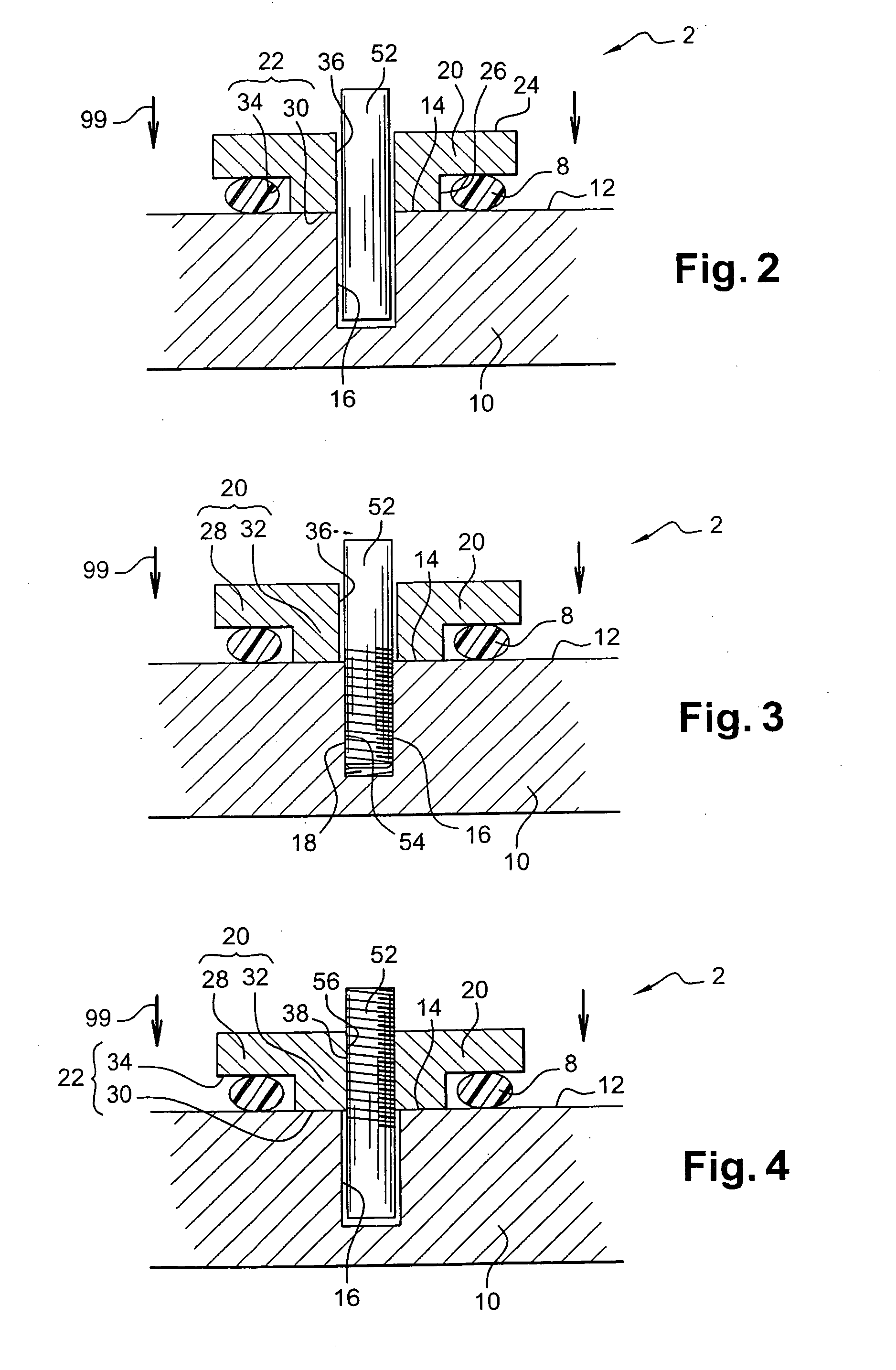
[0063] shown in FIGS. 2 to 5, the connection device 2 comprises a contact part 20, a seal 8 and fastening means 18, 36, 38, 52, 54, 56, 58, 60, 62, 64 for fastening the connection device 2 onto the support 10.

[0064] The contact part 20 is a conducting part that will come into contact with the contact area 14 of the conducting support face 12. It is preferably made of a conducting material, for example such as steel with a surface treated against corrosion. It comprises a first face 22 and a second face 24 substantially opposite the first face. The first face 22 comprises a peripheral face 30 and a central face 34 that are delimited by a shoulder 26, and that correspond to a peripheral part 28 and a central part 32 of the contact part 20, respectively. The second face 24 of the contact part 20 is preferably substantially plane.

[0065] The seal 8 is designed to keep the contact area 14 of the conducting face 12 air tight to prevent it from corroding. The seal 8 is preferably an O-rin...

second embodiment

[0077] shown in FIGS. 6 to 8, the connection device 2 comprises two contact parts 20, two seals 8 and fastening means 36, 60, 62, 64, 66, 70, 72, 76, 78, 80, 82 of the connection device 2 onto the support 10. It is particularly adapted to a support 10 comprising two electrically conducting faces 12 substantially opposite each other and through which there is a support hole 16 that opens up on each of the two conducting faces 12.

[0078] The two contact parts 20 are preferably similar to each other and similar to the contact part 20 of the first embodiment of the connection device 2.

[0079] The seals 8 are preferably similar to each other and similar to the seal 8 of the first embodiment.

[0080] The fastening means 36, 60, 62, 64, 66, 70, 72, 76, 78, 80, 82 fastening the connection device 2 onto the support 10 are also capable of maintaining electrical contact between each conducting face 12 of the support 10 and the corresponding contact part 20. They comprise: [0081] a hole 36 in on...


PUM


Abstract

The electrical connection device (2) comprises:
    • at least one electrically conducting contact part (20), with first and second substantially opposite faces (22, 24), the first face being provided with a shoulder (26) delimiting a peripheral part (28) with a peripheral face (30), and a central part (32) with a central face (34),
    • at least one seal (8), and
    • means of fastening the device on a support (10), capable of maintaining electrical contact between said support (10) and said contact part (20).
Application for making a metallisation point by fastening an electrical connection device (2) on a support (10) provided with at least one electrically conducting support face (12).

Description

TECHNICAL FIELD [0004] This invention relates to the technical field of electrical connections between conducting elements. [0005] More particularly, it relates to an electrical connection device arranged on an electrically conducting support so as to make an electrical contact point, also called a metallisation point, on this support. Such metallisation points are used to connect the support to an electrically conducting member. This device may for example be a braid fitted with a lug. The electrical connection between the support and the braid is then made by fixing the lug of the braid on the connection device of the support. [0006] This type of connection may be used to make the support equipotential with other electrically conducting elements, for example by electrical grounding so as to prevent accumulation of electrostatic charges on this support, which could cause sudden electrostatic discharges that could create a fire or explosion, which should be avoided. [0007] This type...

Claims


Application Information

Patent Timeline
IPC IPC(8): B64D45/02H01R4/34H01R4/62H01R13/52
CPCB64D45/02H01R13/52H01R4/62H01R4/34
Inventor GIRINON, OLIVIER
Owner AIRBUS OPERATIONS (SAS)
Why Eureka
Try Eureka