
Method of using a small MRI scanner

a technology of mri scanner and mri scanner, which is applied in the field of small mri scanner, can solve the problems of reducing the optimal imaging area, reducing the field stability, and significant cutting of magnet material cost, so as to reduce the radius of the magnet, effectively keeping the same patient, and facilitating patient access

Inactive Publication Date: 2005-07-14
ZHAO LEI +2
View PDF0 Cites 58 Cited by
  • Summary
  • Abstract
  • Description
  • Claims
  • Application Information

AI Technical Summary

Benefits of technology

[0011] This invention is directed to methods of operating a whole body magnetic resonance imaging (MRI) systems that are much more cost-effective than current conventional MRI systems because of reducing the open magnet size and hence the size of RF and gradient coils. The size reduction for these key components results in a significant reduction in cost for magnet materials and for power supplies and amplifiers. Even though cost is lowered with a small scanner size, the imaging quality is preserved by the techniques of this invention. Due to the reduction in scanner size, the present system is more open than all conventional systems (both cylindrical and vertical open) and therefore more suitable for interventional MRI. The systems can either be permanent, electrical or superconducting based magnets.
[0012] A first requirement of the present invention is to reduce the magnet size significantly while keeping the whole body access and the magnetic field strength substantially the same as in conventional whole-body systems. For cylindrical horizontal magnet systems, the bore diameter can be kept the same while the bore length is made 20-30% shorter. For vertical open permanent magnet planar systems, the gap size is substantially maintained while the magnet diameter and total magnet volume are reduced by about 30 to 60% of a conventional system. This directly translates into a significant cutting of magnet material cost.
[0013] Along with the magnet size reduction, the gradient and RF coils are also reduced similarly in physical size. The smaller gradient or RF coils need much less power to achieve the same performance. As a result, the gradient and RF power amplifiers can be reduced significantly. Since the price of amplifiers is strongly related to the power required, the amplifier costs are also significantly reduced. Thus, the gradient and RF amplifier cost, another very expensive part of a MRI system, is also reduced, lowering the total system cost considerably.

Problems solved by technology

This directly translates into a significant cutting of magnet material cost.
A problem with simply reducing magnet, gradient coil and RF coil sizes is that it results in a reduction of optimal imaging area, i.e., the useful imaging area with sufficient field homogeneity, gradient linearity, and RF field homogeneity.
Another problem is a decrease in field stability.
A small scanner, especially a low field permanent magnet system, is more susceptible to temperature drifts than a large conventional scanner.

Method used


Image

  • Method of using a small MRI scanner
  • Method of using a small MRI scanner
  • Method of using a small MRI scanner

Examples


Embodiment Construction

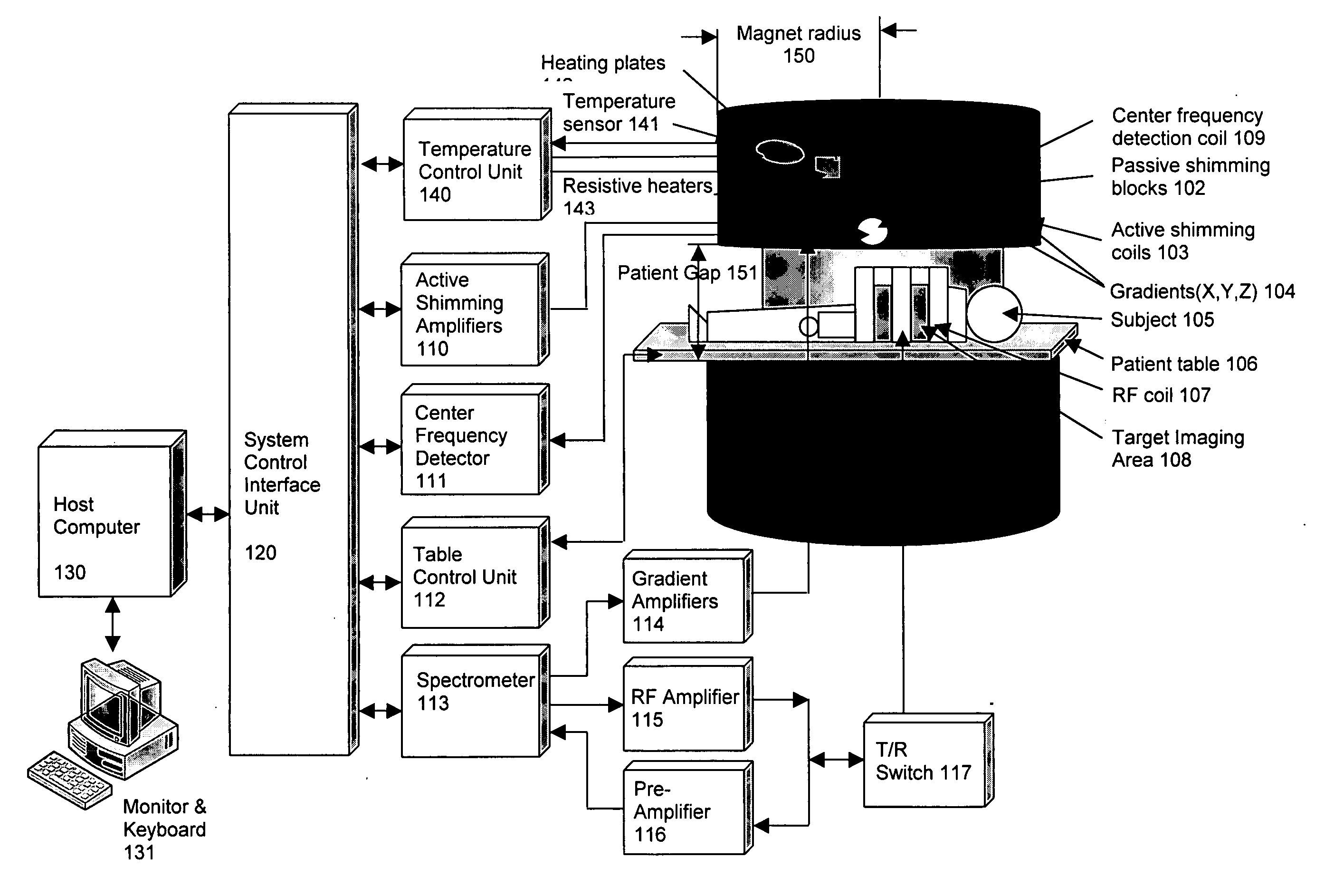
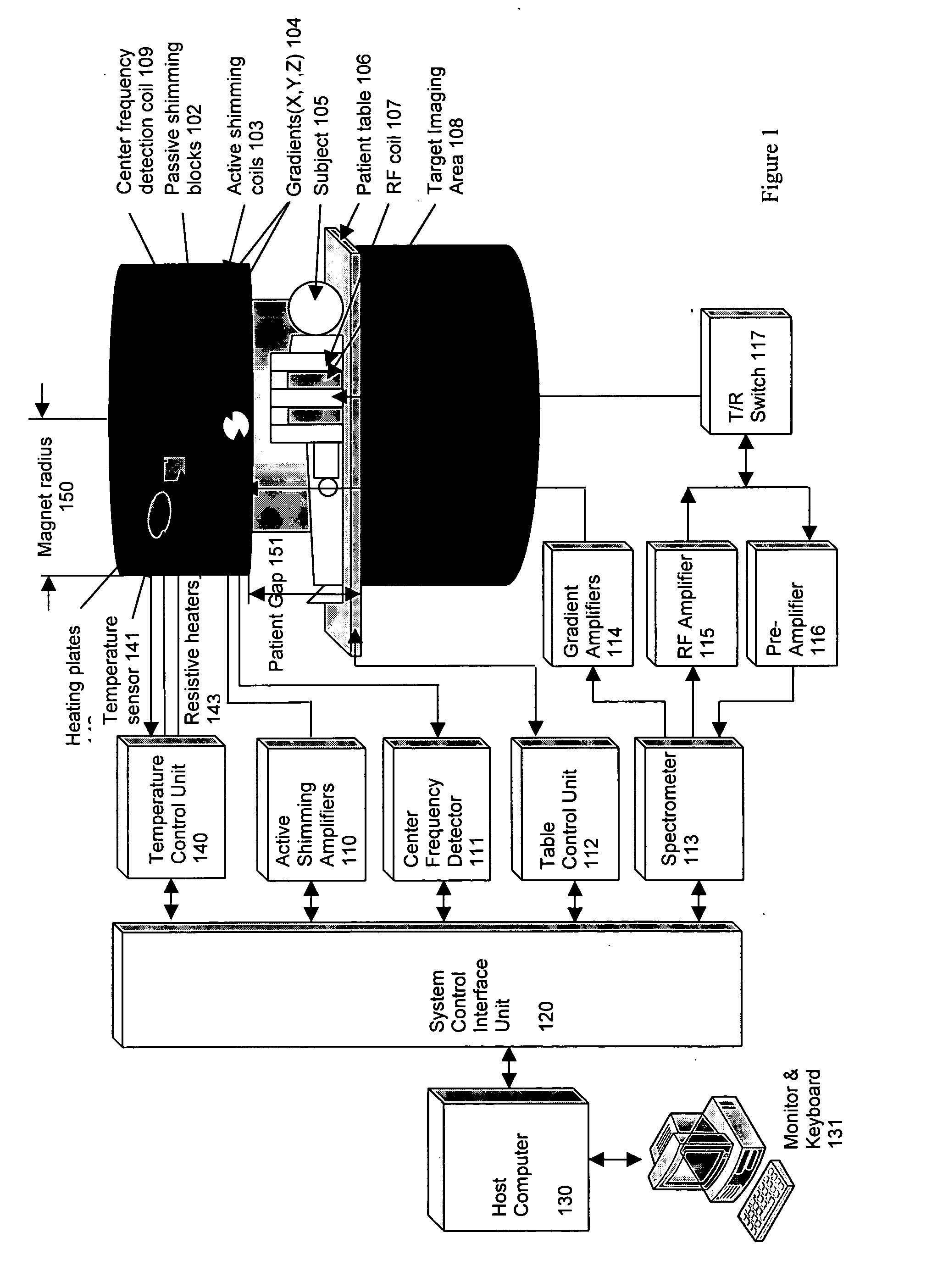
[0030]FIG. 1 illustrates a simplified block diagram of a MRI system for producing images in accordance with embodiments of the present invention. The system could have an open, cylindrical shaped electrical, superconducting, or a permanent magnet. An open, cylindrical permanent magnet is shown as an example in FIG. 1.

[0031] In the embodiment of this invention, the static magnet field is provided by the magnet 101 as shown in FIG. 1. In the preferred embodiment of this invention and as shown in FIG. 1 the field is oriented vertically; however, this invention applies to any other types of magnets and field orientation as well. Passive shimming blocks 102, mounted on the inner surfaces of the magnet, are used for improving the homogeneity of the magnetic field. These passive shimming blocks 102 are usually ferrite or high permeability materials. To further improve field homogeneity, active shimming coils 103 are also mounted within the gradient coils 104. The shimming coils generate, ...


PUM


Abstract

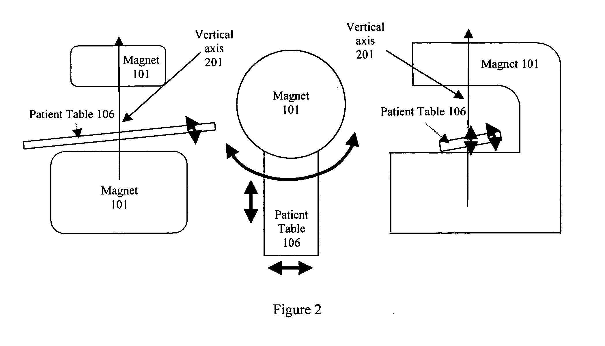
Multiple methods of performing whole body scans using a cost-effective small magnetic resonance imaging (MRI) system are disclosed. High magnetic field homogeneity of an open, small MRI is obtained by a combination of passive shimming and high order active shimming. A dynamic shimming while imaging (DSWI) method is provided to dynamically optimize field homogeneity for each scanned slab (slice) during imaging. Also provided is a method that scan a large subject volume only using a limited optimal imaging region of a magnet by continuously adjusting patient position and orientations with a 6 degrees of freedom patient table.

Description

PRIORITY CLAIM [0001] This application claims priority from U.S. Provisional Application 60 / 505,015, filed Sep. 19, 2003.BACKGROUND OF THE INVENTION [0002] Whole body imaging using magnetic resonance (MR) technology has been used for years. The cost of a whole body system is still extremely high, preventing it from being accessed worldwide, especially in rural settings, developing countries and emergency rooms of developed countries. These costs are driven by the major hardware that comprises an MRI system: the magnet, cryogenic systems, gradient coils, rf coils, patient table, the various amplifiers and image acquisition and processing subsystems. A whole body scanner typically requires a large enough magnet opening to accommodate whole body scans with sufficient magnetic field homogeneity, rf field homogeneity and enough rf power over large volumes to generate sufficient excitation, sufficient gradient linearity over a large volume, strength and slew rate to generate images of acc...

Claims


Application Information

Patent Timeline
IPC IPC(8): G01R33/38G01R33/3873G01R33/3875G01R33/563
CPCG01R33/3806G01R33/56375G01R33/3875G01R33/3873
Inventor ZHAO, LEITEKLEMARIAM, GRUMLIAN, JIANYU
Owner ZHAO LEI
Learn More