
Method and apparatus for trephinating body vessels and hollow organ walls

a hollow organ wall and body vessel technology, applied in the field of surgical instruments and devices, can solve problems such as dragging cuts

Inactive Publication Date: 2005-07-14
BREZNOCK EUGENE M +1
View PDF28 Cites 70 Cited by
  • Summary
  • Abstract
  • Description
  • Claims
  • Application Information

AI Technical Summary

Benefits of technology

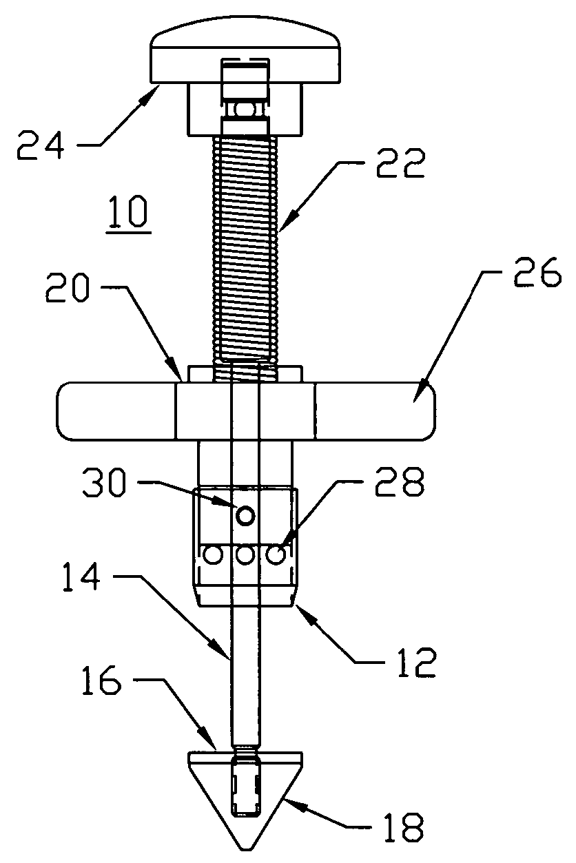
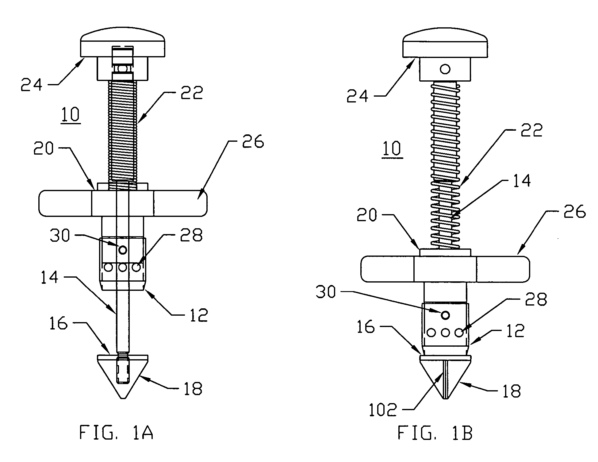
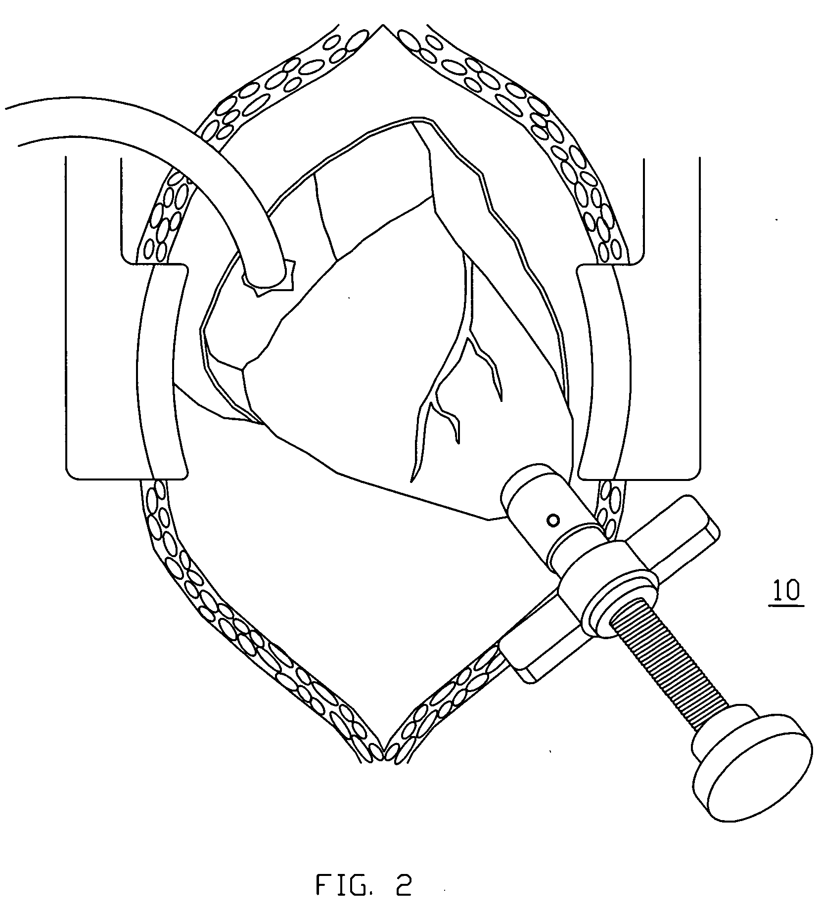
[0006] This invention relates to a trephine, coring tool, or punch for creating a hole or stoma at a precise, desired location in a hollow organ or body vessel. The present invention is a cutting surface or edge that is opposed by an anvil to create a clean cut. The anvil comprises a tapered nose to facilitate penetration into the organ or vessel once a preliminary incision has been performed. The cutting surface or edge is spring loaded to perform the actual cutting under pre-assigned force. The system allows for location reference by allowing the punch to rest, under spring, or otherwise generated, force, against the tissue to be cut while final alignment is completed, thus allowing a more accurate cut. The system further provides for rotation of the cutting surface or edge as it approaches the anvil. Preferably, the cutting edge rotation is substantial, and greater than ¼ revolution (90 degrees) as it approaches, or is approached by, the anvil. The anvil in this type of system may be described as a Hammer Anvil since the face of the anvil that faces the cutting surface serves as a stop for the cutting surface as the distance between the anvil and the cutting surface or edge is reduced to zero.

Problems solved by technology

Both of these methods produce a ragged cut.

Method used


Image

  • Method and apparatus for trephinating body vessels and hollow organ walls
  • Method and apparatus for trephinating body vessels and hollow organ walls
  • Method and apparatus for trephinating body vessels and hollow organ walls

Examples


Embodiment Construction

[0026] The invention may be embodied in other specific forms without departing from its spirit or essential characteristics. The described embodiments are to be considered in all respects only as illustrative and not restrictive. The scope of the invention is therefore indicated by the appended claims rather than the foregoing description. All changes that come within the meaning and range of equivalency of the claims are to be embraced within their scope.

[0027] The invention, which is generally termed a surgical instrument, can be described as being an axially elongate structure having a proximal end and a distal end. The axially elongate structure further has a longitudinal axis. As is commonly used in the art of medical devices, the proximal end of the device is that end that is closest to the user, typically a surgeon. The distal end of the device is that end closest to the patient or that is first inserted into the patient. A direction being described as being proximal to a ce...


PUM


Abstract

A system is disclosed for creating a hole in a body vessel or hollow organ. Such holes are useful in surgically preparing the hollow organ or body vessel for connection with another hollow organ, body vessel or prosthetic conduit. For example, an assist device is generally connected to the left ventricle through a ventriculotomy created at the apex of the left ventricle. This ventriculotomy is most easily created with a punch or trephine. Control over such a procedure must be precise so as not to damage the ventricular wall or intracardiac structures such as papillary muscles, chordae tendinae, etc. The punch of the current invention allows for precise location and alignment of the cutting segment. The punch of the current invention also allows for precise advance of the cutting blade and a very clean cut of the tissue. Such clean cuts improve the healing when the hole in the body vessel or hollow organ is closed or attached to a connection, either prosthetic or natural.

Description

PRIORITY INFORMATION [0001] This application is a continuation-in-part of U.S. patent application Ser. No. 09 / 938,428, filed Aug. 23, 2001, now U.S. Pat. No. 6,863,677.FIELD OF THE INVENTION [0002] The field of this invention is related to instrumentation and devices for surgery and especially, interventional, cardiovascular, general or peripheral vascular surgery. BACKGROUND OF THE INVENTION [0003] During surgical procedures such as placement of a ventricular assist device, blood vessel anastomosis, aortotomy, gastrotomy, enterotomy, or access to other hollow organs and vessels, it is useful to have a specialized tool to create a circular opening or fenestration in the wall of the vessel or organ. Punches have been developed for use in surgery that create such fenestrations. Examples of the prior art include U.S. Pat. No. 3,776,237 to Hill, U.S. Pat. No. 3,949,747 to Hevesy, U.S. Pat. No. 4,018,228 to Goosen, U.S. Pat. No. 4,122,855 to Tezel, U.S. Pat. No. 4,216,776 to Downie et al...

Claims


Application Information

Patent Timeline
IPC IPC(8): A61B17/00A61B17/11A61B17/32A61B17/34
CPCA61B17/320016A61B17/32053A61B17/3417A61B2018/00392A61B2017/1107A61B2017/1135A61B2017/00247
Inventor BREZNOCK, EUGENE M.LENKER, JAY A.
Owner BREZNOCK EUGENE M
Learn More