Processing apparatus and processing apparatus maintenance method

a technology for processing apparatuses and maintenance methods, applied in the direction of lighting and heating apparatus, heating types, domestic cooling apparatus, etc., can solve the problems of significant energy loss and the installation area of apparatuses, and achieve the effect of reducing the required installation area and saving energy

Inactive Publication Date: 2005-07-21
TOKYO ELECTRON LTD
View PDF13 Cites 78 Cited by
  • Summary
  • Abstract
  • Description
  • Claims
  • Application Information

AI Technical Summary

Benefits of technology

[0010] An object of the present invention, which has been completed by addressing the problems of the cooling mechanism in the processing apparatus in the related art discussed above, is to provide a new and improved temperature control device for an electrode in a processing apparatus, that achieves a reduction in the required installation area through miniaturization of the electrode temperature control device and also achieves energy saving.

Problems solved by technology

The cooling mechanism in the processing apparatus adopting the structure described above requires two circuits, i.e., a primary coolant circulating circuit constituted with a coolant tank, a pump and the like and a freezing circuit (a secondary coolant circulating circuit) constituted with a compressor, a condenser, an expansion valve and an evaporator, and thus a problem arises in that the apparatus requires a significant installation area.
In addition, there is another problem in that since heat is exchanged multiple times between the workpiece and the primary coolant, between the primary coolant and the secondary coolant, and between the secondary coolant and the atmosphere in the structure having the two circuits, the extent of energy loss is bound to be significant.

Method used


Image

  • Processing apparatus and processing apparatus maintenance method
  • Processing apparatus and processing apparatus maintenance method
  • Processing apparatus and processing apparatus maintenance method

Examples


Embodiment Construction

[0025] The following is a detailed explanation of a preferred embodiment of the processing apparatus and the processing apparatus maintenance method according to the present invention, given in reference to the attached drawings. It is to be noted that in the specification and drawings, the same reference numerals are assigned to components having substantially identical functions and structural features to preclude the necessity for a repeated explanation thereof.

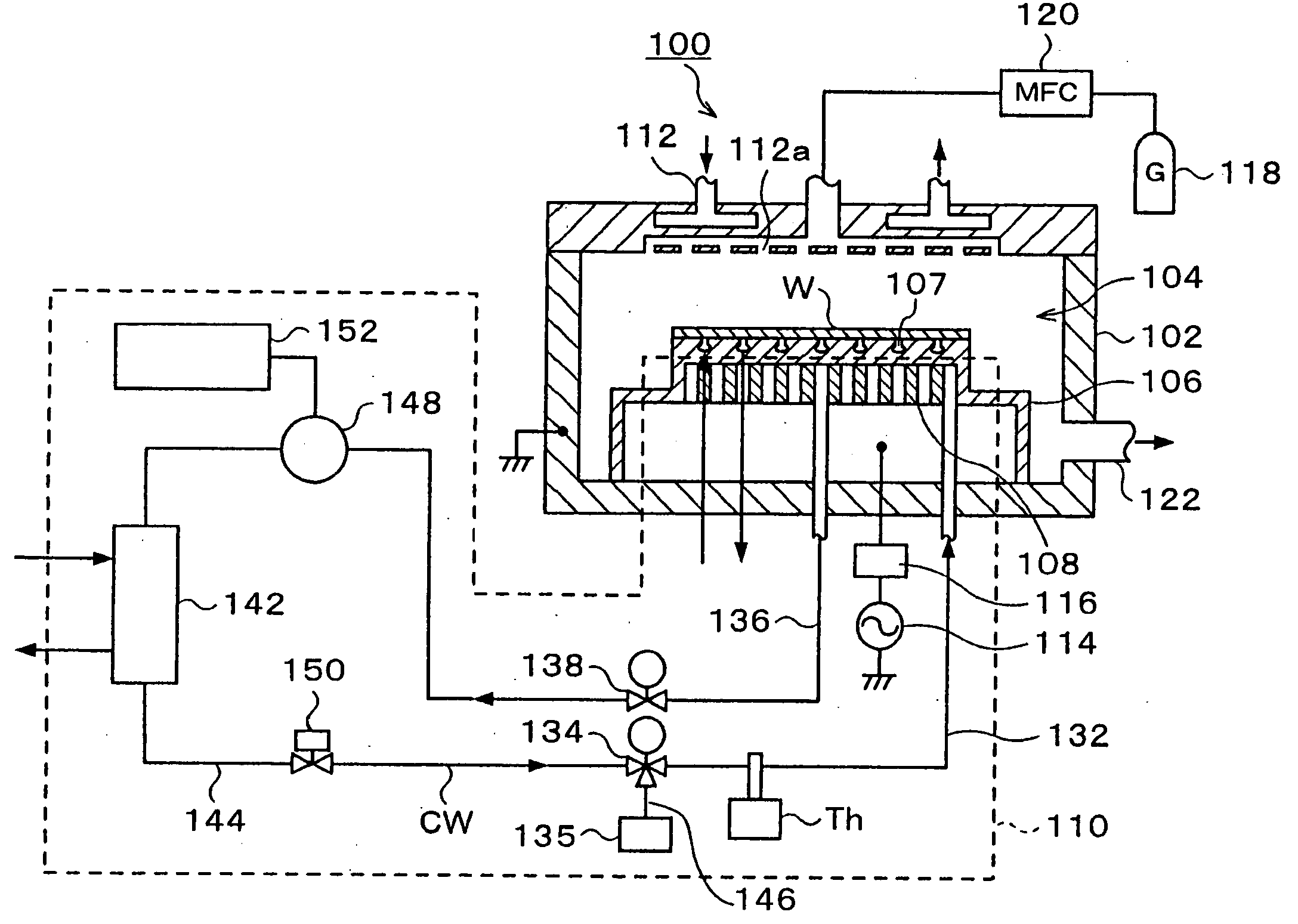
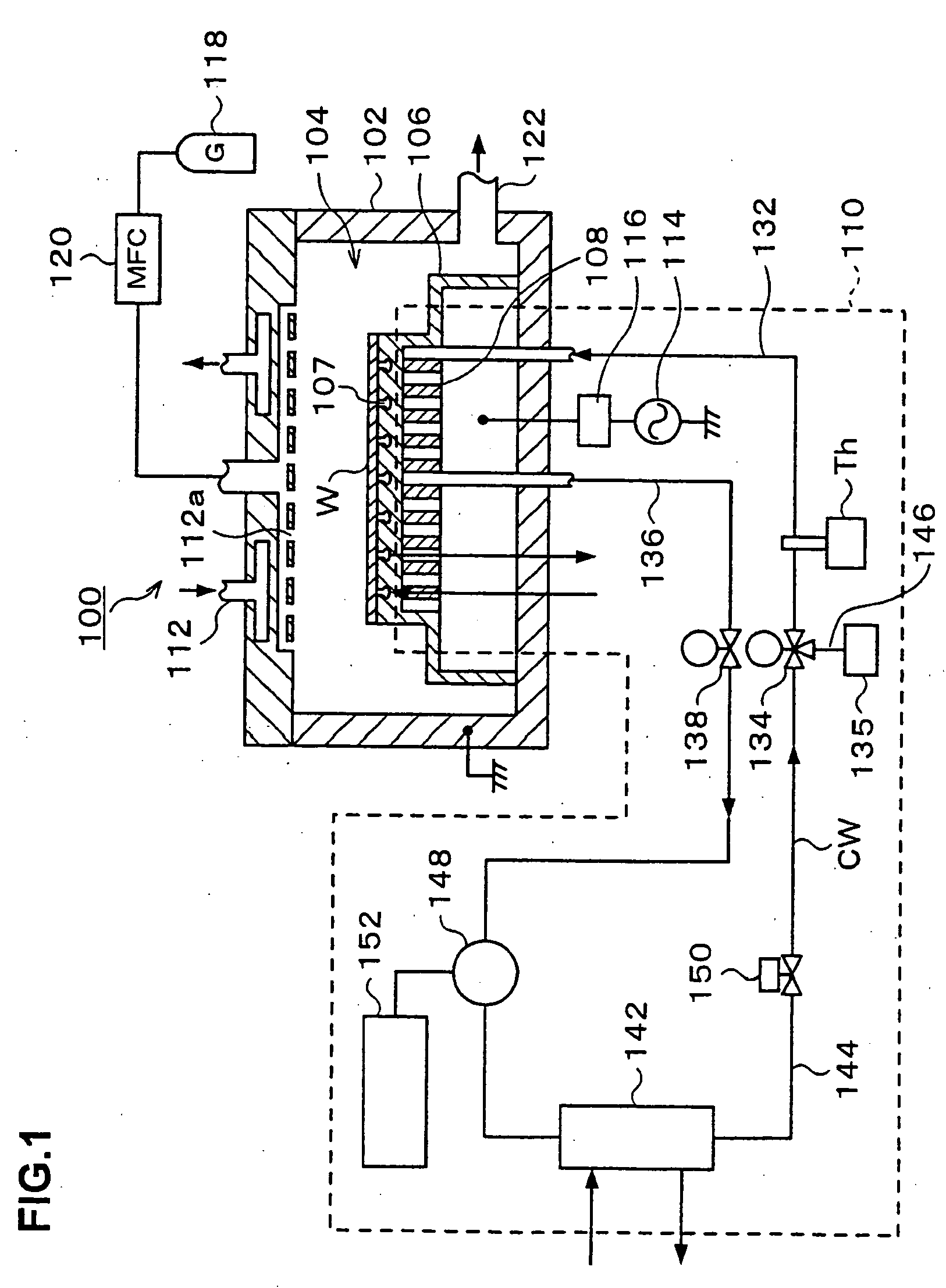
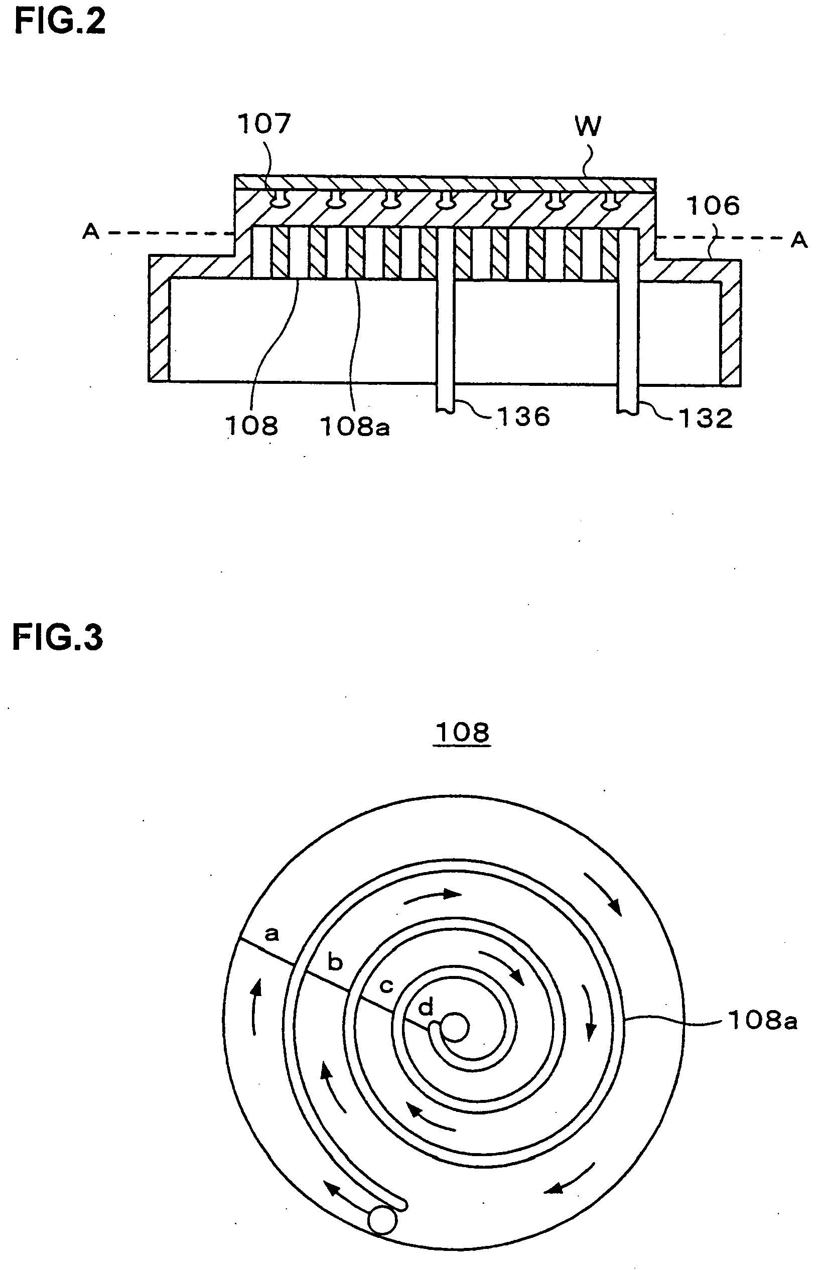
[0026] A first feature characterizing the embodiment is that a coolant-circulating path disposed inside a lower electrode is constituted with a heat-transferring wall to allow the coolant-circulating path to function as an evaporator constituting part of the freezing circuit. A second feature characterizing the embodiment is that CO2 is used as the coolant.

(1) Electrode Temperature Control Device in Processing Apparatus

[0027] First, a plasma etching apparatus 100 representing an example of the processing apparatus is e...


PUM


Abstract

The electrode temperature control device in a processing apparatus 100 includes a freezing circuit 110 comprising a compressor 148, a condenser 142, an expansion valve 150 and an evaporator 108 with the evaporator disposed inside a lower electrode 106. This electrode temperature control device does not require components such as a coolant tank for storing the coolant, a pump for supplying the coolant to the processing apparatus, a heater for adjusting the temperature of the coolant and a heat exchanger for exchanging heat between a primary coolant and a secondary coolant. Thus, the production cost can be lowered, a reduction in installation area through miniaturization of the apparatus is achieved and more efficient use of energy is achieved as well. In addition, by using CO2 as the coolant, the GWP value can be reduced to approximately {fraction (1/8000)} to {fraction (1/7000)} that of Freon.

Description

CROSS REFERENCE TO RELATED APPLICATIONS [0001] This is a continuation application of PCT International Application No.PCT / JP03 / 11212 filed Sep. 2, 2003, which claimed priority of Japanese Patent Application No.2002-263761, filed Sep. 10, 2002.BACKGROUND OF THE INVENTION [0002] 1. Field of the Invention [0003] The present invention relates to a processing apparatus and a processing apparatus maintenance method. [0004] 2. Description of Related Art [0005] Various types of processing apparatuses including a plasma etching apparatus are used in the manufacturing of semiconductor devices or LCD substrates in the related art. The plasma etching apparatus, for instance, etches a workpiece such as a semiconductor wafer or a glass substrate placed on an electrode (a lower electrode) with plasma generated from a specific type of process gas inside a vacuum-processing chamber. During the etching process, the temperature of the workpiece is maintained at a specific level so as to ensure that th...

Claims


Application Information

Patent Timeline
Patent Type & Authority Applications(United States)
IPC IPC(8): F25B9/00F25B39/02F28D7/04H01J37/32H01L21/00
CPCF25B9/008F25B39/02F25B2309/06H01L21/67109H01J37/32724H01J2237/2001F28D7/04
Inventor HIROOKA, TAKAAKIFURUYA, MASAOTSUTSUMI, SHOHEI
Owner TOKYO ELECTRON LTD
Why Eureka
Try Eureka