Linear actuator

Active Publication Date: 2005-07-21
NSK LTD
View PDF8 Cites 103 Cited by
  • Summary
  • Abstract
  • Description
  • Claims
  • Application Information

AI Technical Summary

Benefits of technology

[0005] The present invention, which was devised in view of the problems inherent in the prior art described above, aims at providing a line

Problems solved by technology

Besides, the power transmission from the driven member to the electric motor can be hindered while permitting the p

Method used


Image

  • Linear actuator
  • Linear actuator
  • Linear actuator

Examples


first embodiment

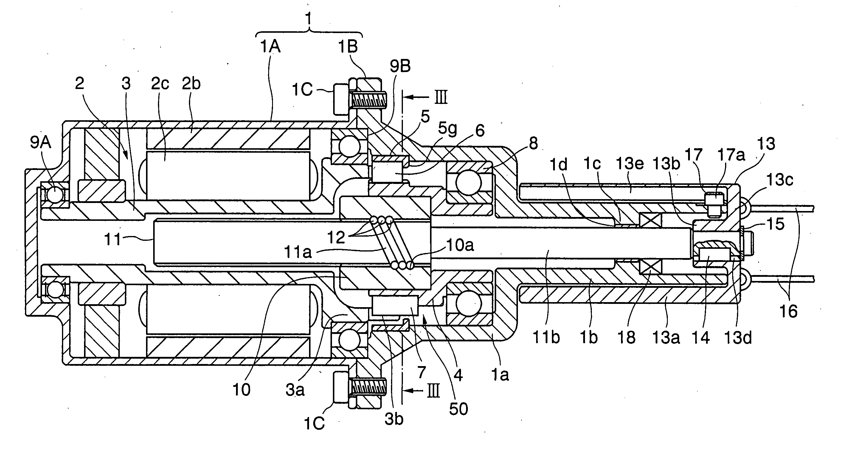
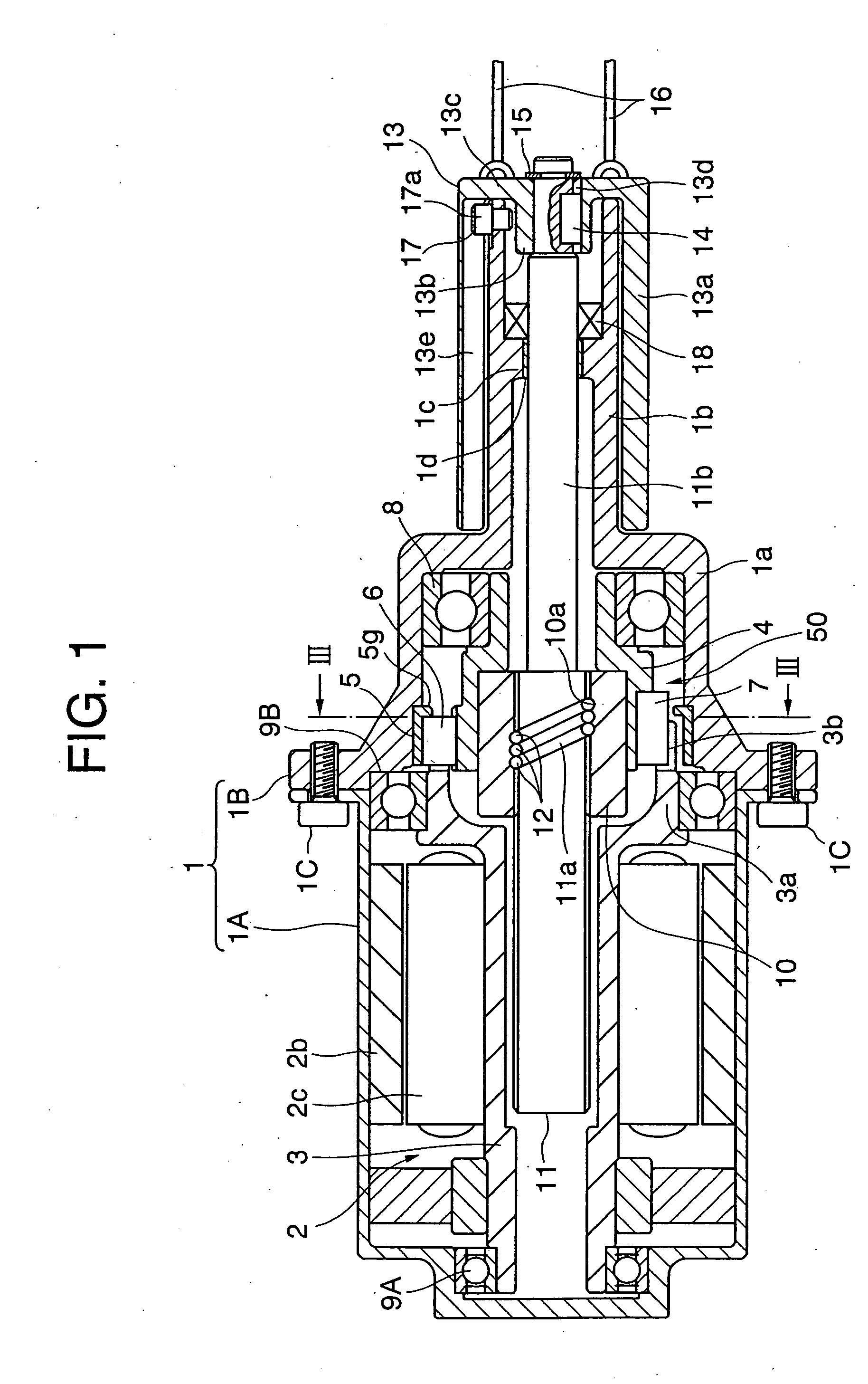
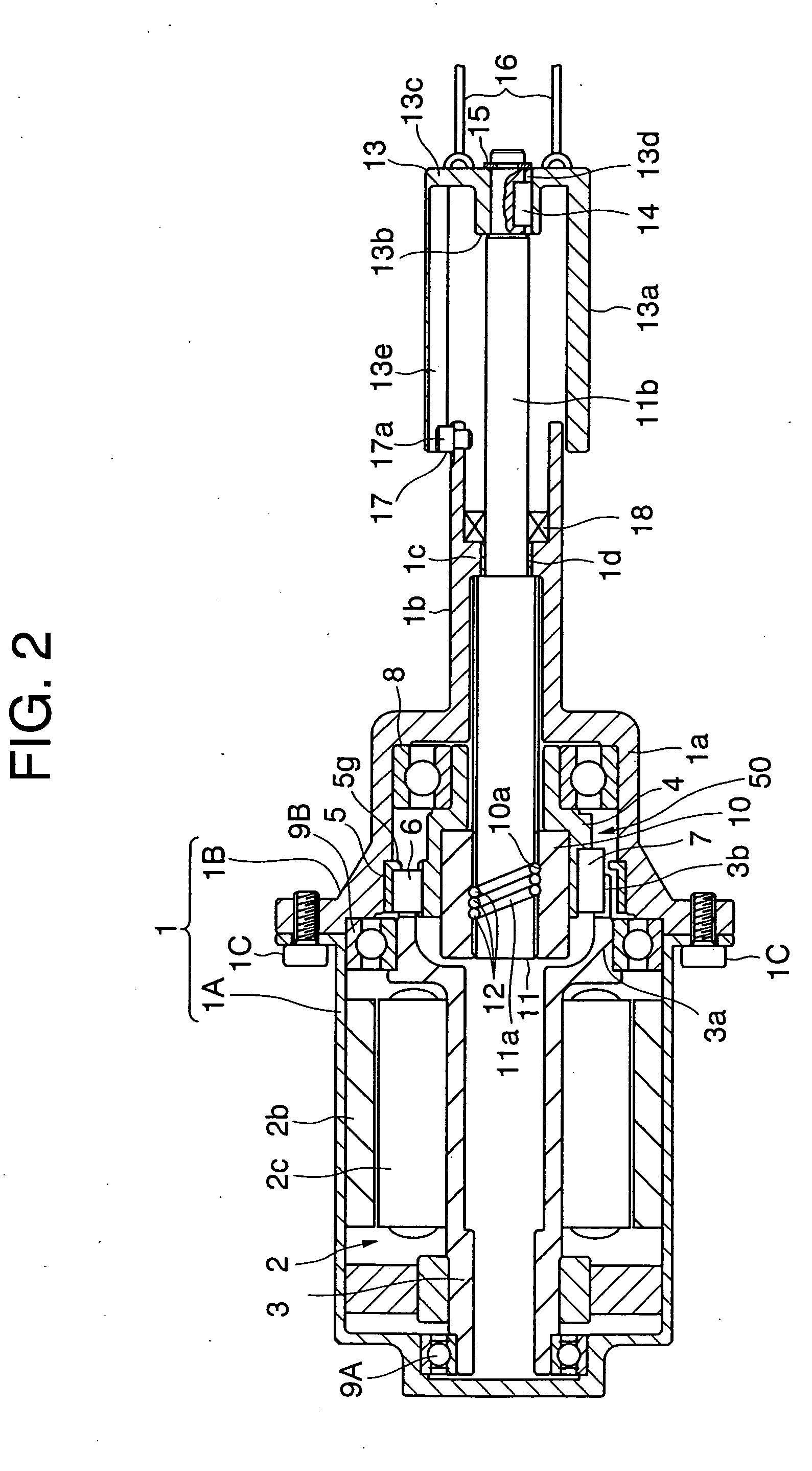
[0068] Next, embodiments of the present invention will hereinafter be described with reference to the drawings. FIG. 1 is a sectional view of an electric parking brake drive apparatus when in a braking operation by way one example of a linear actuator in a FIG. 2 is a sectional view of this type of electric parking brake drive apparatus when released from braking. FIG. 3 is a view showing a construction cut off along the line III-III in FIG. 1 as viewed in an arrowhead direction.

[0069] In FIG. 1, housing 1 is constructed of cylindrical motor housing 1A and cylindrical main housing 1B that are connected to each other via a bolt 1C. A cylindrical stator 2b is fixed to an inner peripheral surface of the motor housing 1A, and embraces a rotor 2c. The rotor 2C is attached to an outer peripheral surface of a rotary shaft 3 of which a left side end is, as viewed in FIG. 1, rotatably supported via a bearing 9A with respect to the motor housing 1A, whereby the rotary shaft 3 and the rotor 2...

fifth embodiment

[0089]FIG. 8 is a sectional view of a linear actuator according to a FIG. 9 is an enlarged view of a portion indicated by an arrowhead IX in the construction in FIG. 8. FIG. 10 is a view of the construction as viewed in an arrowhead direction in a way that cuts off the construction along the line X-X.

[0090] In FIG. 8, main housing 101B taking a substantially cylindrical shape is fitted via an O-ring 101C in an aperture Ca of a box body C and is thus secured to the box body C together with cylindrical motor housing 101A by use of an unillustrated bolt. Housing 101 is constructed of the motor housing 101A and the main housing 101B. An electric motor 102 including a rotary shaft 103 defined as an output shaft is disposed inwardly of the motor housing 101A.

[0091] The rotary shaft 103 is rotatably supported via a bearing 109A with respect to the motor housing 101A at a left side end in FIG. 8. The bearing 109A is biased by a washer spring 120 toward a right side in FIG. 8 against the m...

sixth embodiment

[0117] In the sixth embodiment, when at least part (the pawl portion 203b within a range Y2 in FIG. 11) of the axis-directional engagement portion between the rotary shaft 201 as the rotation driving portion and the rotation driven member 204 as the rotation driven portion exists in a range (an axis-line-directional extension range Y1 of a tube 210c in FIG. 11) where the ball 212 of the ball screw mechanism (212, 210, 211) exits, it is possible to restrain an adverse effect that is exerted on the nut 210 by the moment generated at the engagement portion (the pawl portion 203b) due to an axis deviation between the electric motor 202 and the nut 210.

[0118] A power transmission mechanism 250 includes the rotary shaft 203 as the rotation driving portion, the rotation driven member 204 as the rotation driven portion, the outer race 205 as the fixing portion, and the ball screw mechanism (211, 210, 211) as a converting mechanism.

[0119] A construction of the power transmission mechanism 2...


PUM


Abstract

A rotary shaft (3) and a rotation driven member (4) are so connected as to be capable of transmitting motive power when the rotary shaft (3) rotates relatively to the rotation driven member (4). A roller (6) gets displaced to a first position where a frictional force with an outer race (5) and the rotation driven member (4) decreases, thereby permitting transmission of a rotational force from the rotary shaft (3) to the rotation driven member (4). When the rotation driven member (4) rotates relatively to the rotary shaft (3), the roller (6) gets displaced to a second position where the frictional force with the outer race (5) and the rotation driven member (4) increases, thereby rotationally fixing the rotation driven member (4) with respect to the outer race (5). The power transmission from a brake apparatus (e.g., a parking brake apparatus) to an electric motor (2) can be hindered while permitting the power transmission to the brake apparatus from the electric motor (2) by using neither a worm exhibiting a relatively low transmission efficiency nor a worm wheel. In a state where the brake apparatus exhibits its braking force, the roller (6) receives the force from the brake apparatus and is thereby biased toward the second position, whereby a construction of a power transmission mechanism (50) can be simplified and costs can be reduced to such an extent.

Description

TECHNICAL FIELD [0001] The present invention relates to a linear actuator using an electric motor as a power source that can be applied to, for example, a power window of an automobile, a wire winding mechanism of an electric parking brake apparatus, a caliper extrusion mechanism of an electric disk brake apparatus, a cam phase converting mechanism in a valve timing variable apparatus of an engine, a belt CTV pulley drive mechanism, etc., a 2-wheel-drive / 4-wheel-drive switching mechanism of a 4WD apparatus, and other industrial apparatuses such as a winch, a hoist, a crane and a variety of positioning apparatuses. BACKGROUND ARTS [0002] Known, for instance, is a linear actuator for an electric parking brake drive apparatus, etc., which reduces a load on a driver by employing motive power of an electric motor when operating a parking brake of a vehicle. This type of linear actuator is proposed, wherein a parking brake is operated by wining up a cable in a way that rotates a pulley wi...

Claims


Application Information

Patent Timeline
IPC IPC(8): F16D65/14F16D65/18F16H25/20F16H25/22F16H25/24F16H63/48H02K7/06H02K7/08
CPCB60T13/746F16D65/28F16D2121/24F16D2125/40F16H25/2204Y10T74/18688H02K7/06H02K7/083Y10T74/18704Y10T74/18568Y10T74/18696F16H25/2454
Inventor OTAKI, RYOICHIYAMASHITA, TOMOFUMI
Owner NSK LTD
Why Eureka
Try Eureka