Outdoor gas fireplace

a gas fireplace and outdoor technology, applied in the field of outdoor fireplaces, can solve the problems of difficult operation of wood burning fireplaces, difficulty in starting fires in wood burning fireplaces, and difficulty in operating a wood burning firepla

Inactive Publication Date: 2005-07-21
HNI TECH INC
View PDF54 Cites 0 Cited by
  • Summary
  • Abstract
  • Description
  • Claims
  • Application Information

AI Technical Summary

Benefits of technology

[0008] To attain this, the present invention generally comprises a combustion chamber defined by a combustion chamber enclosure, a front panel, and an air intake / gas exhaust system. The air intake / gas exhaust system is defined by a bottom intake defining at least one bottom intake opening, a top exhaust defining at least one top exhaust opening, and a pair of side grille bars at least partially covering a pair of side intake / exhaust openings. The design of the present invention allows the burner assembly to be placed low to the ground surface without the need for a plenum underneath the burner assembly. Additionally, the unique air flow design removes the need for a venting apparatus out the top or back of the fireplace as in most indoor fireplace assemblies.
[0009] Air is drawn in through the bottom intake openings and the lower portions of the intake / exhaust openings that are at least partially covered by side grille bars, and exhaust gases are expelled out the top exhaust openings and the upper portions of the intake / exhaust openings that are at least partially covered by the side grille bars. This circular flow provides for a clean burning, attractive outdoor fireplace.

Problems solved by technology

Outdoor fireplaces are commonly wood burning and are often limited to small devices placed on decks or patios for holding firewood.
These fireplaces are often impractical to use when the wind is blowing or the weather is intemperate.
Starting a fire in a wood burning fireplace is often problematic for the operator.
While these fireplaces may be suitable for the particular purpose to which they address, they are not as suitable for providing an efficient, appealing and hassle-free method of enjoying a fire outdoors.
These requirements for typical gas fireplaces limit the design options and locations that a fireplace can be installed.

Method used


Image

  • Outdoor gas fireplace
  • Outdoor gas fireplace
  • Outdoor gas fireplace

Examples


Embodiment Construction

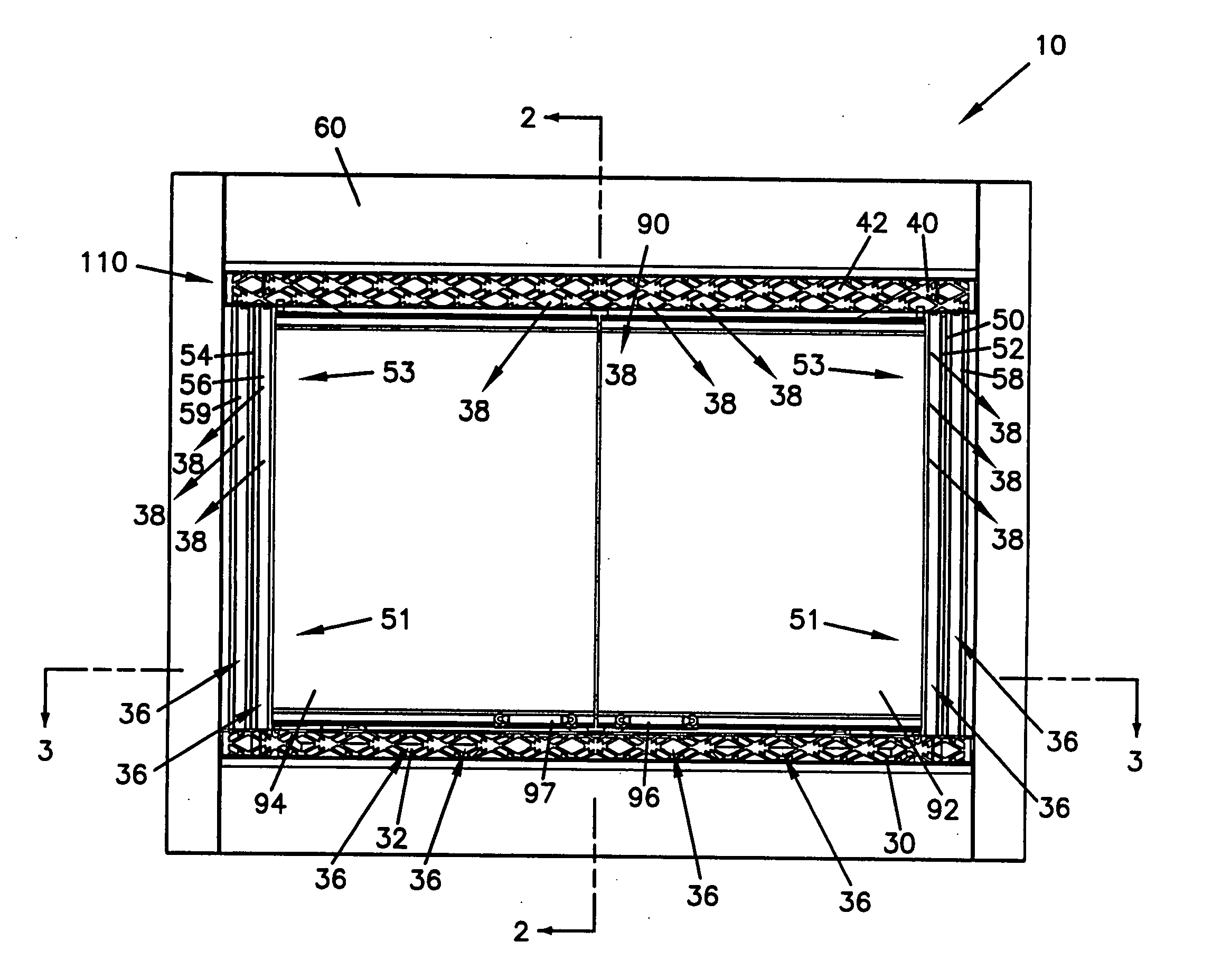
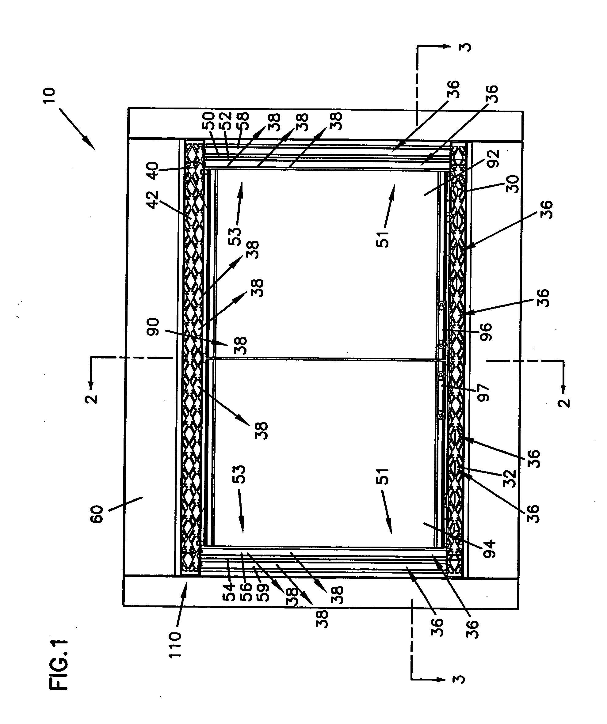
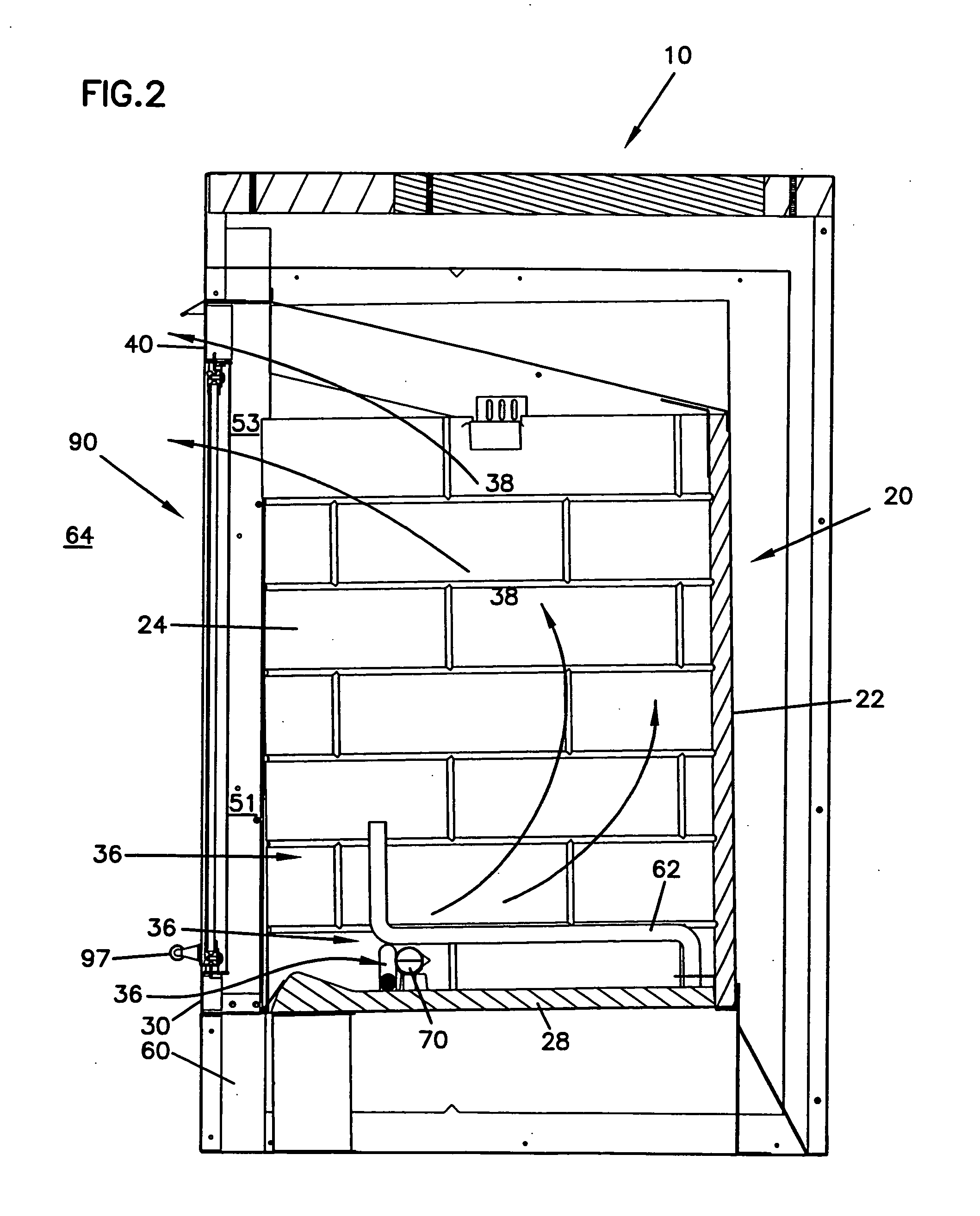
[0023] Referring to FIGS. 1-4 an outdoor gas fireplace 10 is illustrated, which includes a combustion chamber enclosure 20 with a front opening 26. The front opening 26 is at least partially covered by a front panel 90. An air intake / gas exhaust system 110 surrounds at least a portion of the front panel 90. The air intake / gas exhaust system 110 includes a bottom intake 30 defining at least one bottom intake opening 32, a top exhaust 40 defining at least one top exhaust opening 42, and a pair of intake / exhaust openings 50, 54 partially covered by two optional pairs of side grille bars 52, 56 and 58, 59. A gas burner assembly 70 is situated on the floor panel 28 of the combustion chamber enclosure 20.

[0024] The combustion chamber enclosure 20 of the outdoor gas fireplace 10 is defined by a back panel 22, a pair of side panels 23 and 24, a top panel 25, a floor panel 28 and a front opening 26. Alternatively, the combustion chamber enclosure can be configured with any number of panels ...


PUM


Abstract

A fireplace for viewing outside of a house or other structure that includes a combustion chamber defined by a combustion chamber enclosure with a front opening and a front panel at least partially enclosing the front opening. The front panel is partially surrounded by an air intake / gas exhaust system. The air intake / gas exhaust system is defined by bottom intake, a top exhaust and at least one of side intake / exhaust opening. A gas burner is situated on the floor of the combustion chamber enclosure. Fresh air enters through a bottom intake opening in the bottom intake and the lower portion of the intake / exhaust opening. After the combustion exhaust gases are expelled through a top exhaust opening in the top exhaust and the upper portion of the intake / exhaust openings.

Description

CROSS-REFERENCE TO RELATED APPLICATIONS [0001] This application is a continuation of application Ser. No. 10 / 444,316, filed May 22, 2003, which application is incorporated herein by reference.FIELD OF THE INVENTION [0002] The present invention relates to fireplaces. More particularly, the invention relates to a gas fireplace adapted for viewing outside of a house or other structure. BACKGROUND OF THE INVENTION [0003] Fireplaces have been in use for years and are an efficient method for providing warmth and providing the appeal of a fire. Fireplaces have become commonplace in today's building trades for both residential and commercial applications. Most new home construction designs include at least one, and often several fireplaces. Further, a significant number of remodeling projects are focused on fireplaces. Gas, electric, and wood-burning fireplaces are commonly installed to provide benefits such as heat and the aesthetic appeal of a fire. [0004] Outdoor fireplaces are commonly ...

Claims


Application Information

Patent Timeline
Patent Type & Authority Applications(United States)
IPC IPC(8): F24B1/18
CPCF24B1/1808
Inventor STREIT, ROBIN MICHAEL
Owner HNI TECH INC
Why Eureka
Try Eureka