Formulation and method of use for exploitation and transport of heavy and extra heavy oil wells

a technology of oil wells and forms, applied in the direction of fluid removal, chemistry apparatus and processes, borehole/well accessories, etc., can solve the problems of reducing oil production to nil, and achieve the effects of low well productivity, low recovery of original oil in place, and high drag flow pressure loss

Inactive Publication Date: 2015-06-30
INTREVEP SA
View PDF0 Cites 0 Cited by
  • Summary
  • Abstract
  • Description
  • Claims
  • Application Information

AI Technical Summary

Benefits of technology

[0009]As a response to the above problems, especially to the natural oil wet conditions of the sandstone, extremely low well productivity, low recovery of the original oil in place, and high drag flow pressure loss through tubing and surface lines of the heavy and extra heavy oil, the present invention provides a formulation or stimulation fluid and a method of using the formulation for exceptional improvement in all these parameters. Oil in place final recovery of the reservoir, productivity of the well and ease in flow of the heavy and extra heavy oil through pipelines in cold production schemes are accomplished. The result is reflected by a better flow rate in the producing wells, a lower pressure drawdown, an improved oil recovery from the drainage area of the formation and a high capacity of flow of oil as water emulsion to any desired location potentially far away from downhole, to the wellhead and surface conventional facilities. Reservoir patterns of flow of oil are improved in the reservoir as a whole by fluid injection through an injection well in communication with the production well and production stream with areas of very low drag forces achieved by the injection at any desired location in the tubing downhole or at a desired point at surface to the flowline system of another surfactant formulation in an aqueous solution that mixes with the production stream to form an emulsion and reduce the drag forces that are produced by increase in viscosity of the heavy and extra heavy oil as it cools down. Untreated, this could reduce oil production to nil.
[0010]Injection wells are sometimes used as part of a production or exploitation scheme, wherein injection of fluids into one well drives fluids from the area of the injection well to a production well, where production rates are improved.
[0011]The reservoir formulation of the present invention can advantageously be used to improve the flow conditions at both the injection well and the production well and to allow mobilization of oil which is immobile in the porous media due to its affinity to the oil wet surface of the mineral of the rock due to the adsorption of the heavy component of the oil in the mineral surface, and particularly, the asphaltenes. This is done by changing the oil wet condition of the surface to a new water wet condition.

Problems solved by technology

Untreated, this could reduce oil production to nil.

Method used


Image

  • Formulation and method of use for exploitation and transport of heavy and extra heavy oil wells
  • Formulation and method of use for exploitation and transport of heavy and extra heavy oil wells
  • Formulation and method of use for exploitation and transport of heavy and extra heavy oil wells

Examples


example 1

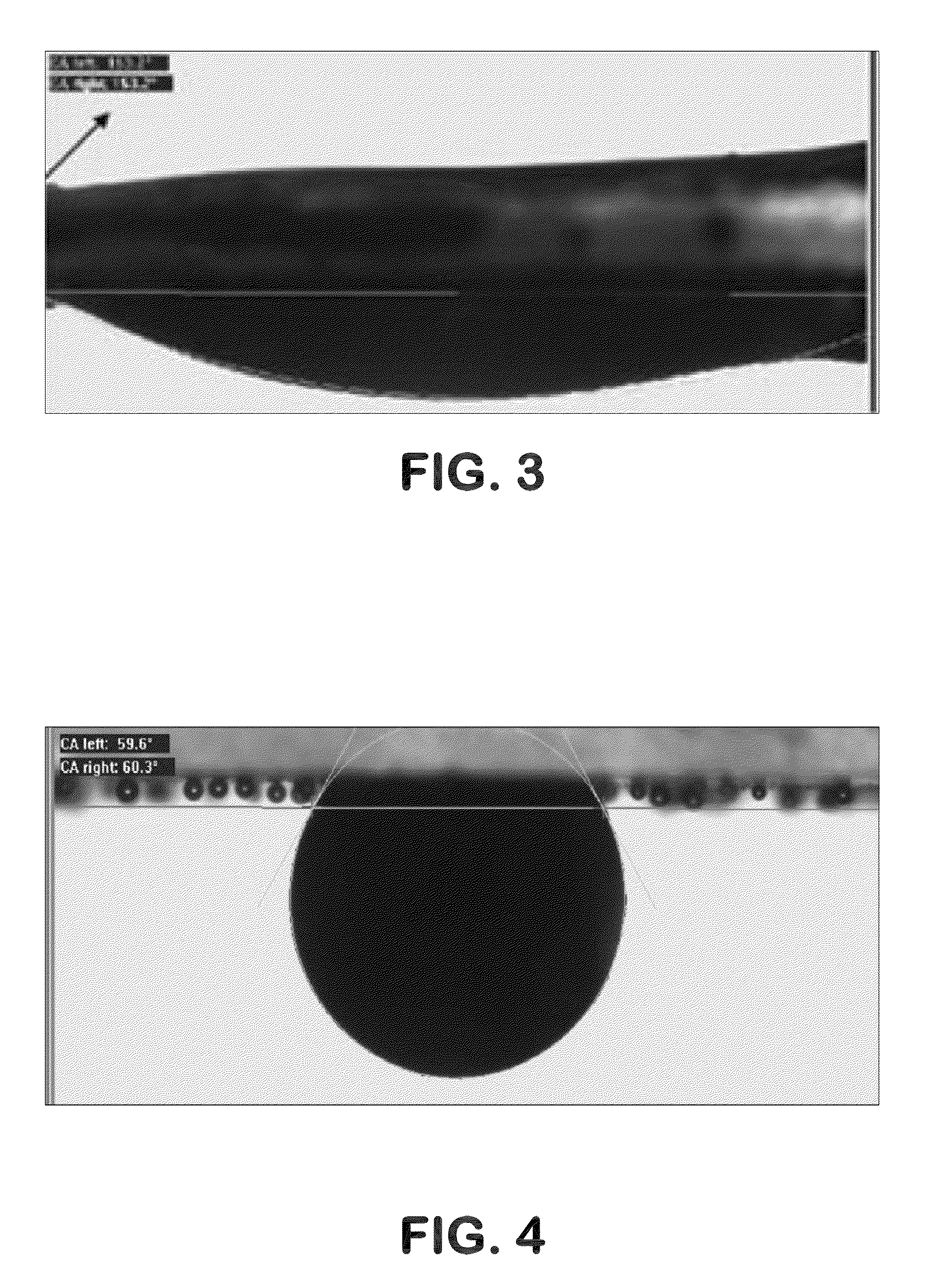
[0077]Crude oil and water from several wells in different areas of the Orinoco River Belt fields were collected. The oil and water were placed in closed glass vessels at several oil and water saturations, at reservoir conditions of water salinity and temperature, in a thermally controlled oven. Inside each vessel was placed a small glass plate which was monitored for wettability conditions starting with a water-wet condition and further being naturally changed to oil wet after a medium time period of about three to four weeks at reservoir temperature of 145° F. For each glass plate, wettability was measured by contact angle measurement techniques at the well temperature ranging from water-wet at the initial condition to oil wet after three weeks of aging process in the vessels at reservoir conditions.

[0078]After this treatment, the glass plates had a contact angle with oil which shows a strongly oil-wet condition as can be seen in FIG. 3, which shows the oil spreading over the plate...

example 2

[0084]A laboratory test was conducted for evaluating relative permeability with extra heavy crude oil and formation water and INTESURF™ 3PW0.5 solution prepared according to the invention with production water from the Cabrutica field of the Junin Division of the Orinoco River Belt Basin in Venezuela, and using a core of well E20P15 and formation fluids of well DE 22 12 of the same field.

[0085]The core from a depth of 2212.2 feet from Cabrutica field was taken, and two samples were packed for use in a confined cell, one sample for return permeability testing and the other sample for relative permeability testing of extra heavy oil and formation water and extra heavy oil and INTESURF 3PW0.5 solution. The samples were cleaned, restored and aged for 16 days at the reservoir temperature of 120° F. and pressure of 400 psi in a confined cell. An imbibition Amott test was performed to both samples to insure an oil wet condition of the sample before the tests. The core properties for two sa...

example 3

[0094]A set of core flow tests were run for relative permeability measurements as shown and described in example 2. Calculations of the K relative to oil (Ko) and K relative to water (Kw) with formation water and with three different concentrations of the Intesurf™ formulation as disclosed in the present invention were done. The formulations were prepared with the production water of the Cabrutica field of the Junin Division of The Orinoco River Belt basin. The surfactant was nonylphenol ethoxylated of 30 EOE and the co surfactant used was methanol. The concentration at 1:1 vv was of 0.5% of each component. During all tests performed with the INTESURF formulation the total injection fluid was injected by several batch with a soaking time of at least a week during the injection of a batches of the injection fluid and another batch to restart flow. With the calculated data a fractional flow of water as a function of the water saturation was calculated for each test of relative permeab...


PUM

PropertyMeasurementUnit
soaking timeaaaaaaaaaa
pressuresaaaaaaaaaa
pressureaaaaaaaaaa

Abstract

A combined injection, production and transportation method includes the steps of introducing a mixture of a surfactant, a co-surfactant and a carrier fluid into each of a production well and an injection well so that the mixture flows into porous media surrounding the production well and the injection well, and holding the reservoir mixture in the porous media surrounding the production well in the presence of water for a period of time sufficient to form a water film on surfaces of the porous media surrounding the production well. An injection fluid is then injected into the injection well while producing from the production well, whereby hydrocarbons flow from the porous media around the injection well toward the production well. An injection mixture of a surfactant and a carrier fluid is injected downhole into a desired point in tubing of the production well so that the tubing injection mixture mixes with the production stream forming an emulsion, and the emulsion flows through the tubing to the wellhead. The emulsion can be transported to intermediate locations and then broken and re-formulated for further transport.

Description

CROSS REFERENCE TO RELATED APPLICATIONS[0001]This application is a continuation-in-part of each of U.S. patent application Ser. No. 12 / 973,022 which was filed on Dec. 20, 2010 and claims the benefit of provisional application Ser. No. 61 / 549,631; U.S. patent application Ser. No. 13 / 474,769 which was filed on May 18, 2012 and claims the benefit of provisional application Ser. No. 61 / 549,631; U.S. patent application Ser. No. 13 / 529,140 which was filed on Jun. 21, 2012 and claims the benefit of provisional application Ser. No. 61 / 549,534; and U.S. patent application Ser. No. 13 / 655,776 which was filed on Oct. 19, 2012 and claims the benefit of provisional application Ser. No. 61 / 549,406.BACKGROUND OF THE INVENTION[0002]The invention relates to a formulation and method of using same for improving well productivity and oil recovery factor in hydrocarbon reservoirs and improving the transportation of said oil through pipelines from downhole to potentially very long distances from the natu...

Claims


Application Information

Patent Timeline
Patent Type & Authority Patents(United States)
IPC IPC(8): E21B43/16C09K8/584C09K8/60
CPCE21B43/16C09K8/602C09K8/584
Inventor MANRIQUE, PABLOARCHER, FRANKLIN
Owner INTREVEP SA
Why Eureka
Try Eureka