Radio frequency identification device with movable antenna

Active Publication Date: 2005-07-21
TWO TECH
View PDF22 Cites 19 Cited by
  • Summary
  • Abstract
  • Description
  • Claims
  • Application Information

AI Technical Summary

Benefits of technology

[0018] The second casing is movably coupled to the first casing so that the second casing can be aligned with the radio frequency identification tag to substantia

Problems solved by technology

This imposes size constraints on the antenna.
The need to repeatedly position the entire reader at a particular orientation when reading the tags can reduce the efficiency and speed with which the user can progress from tag to tag.
Moreover, the location of the tags on the pallets may require the

Method used


Image

  • Radio frequency identification device with movable antenna
  • Radio frequency identification device with movable antenna
  • Radio frequency identification device with movable antenna

Examples


Embodiment Construction

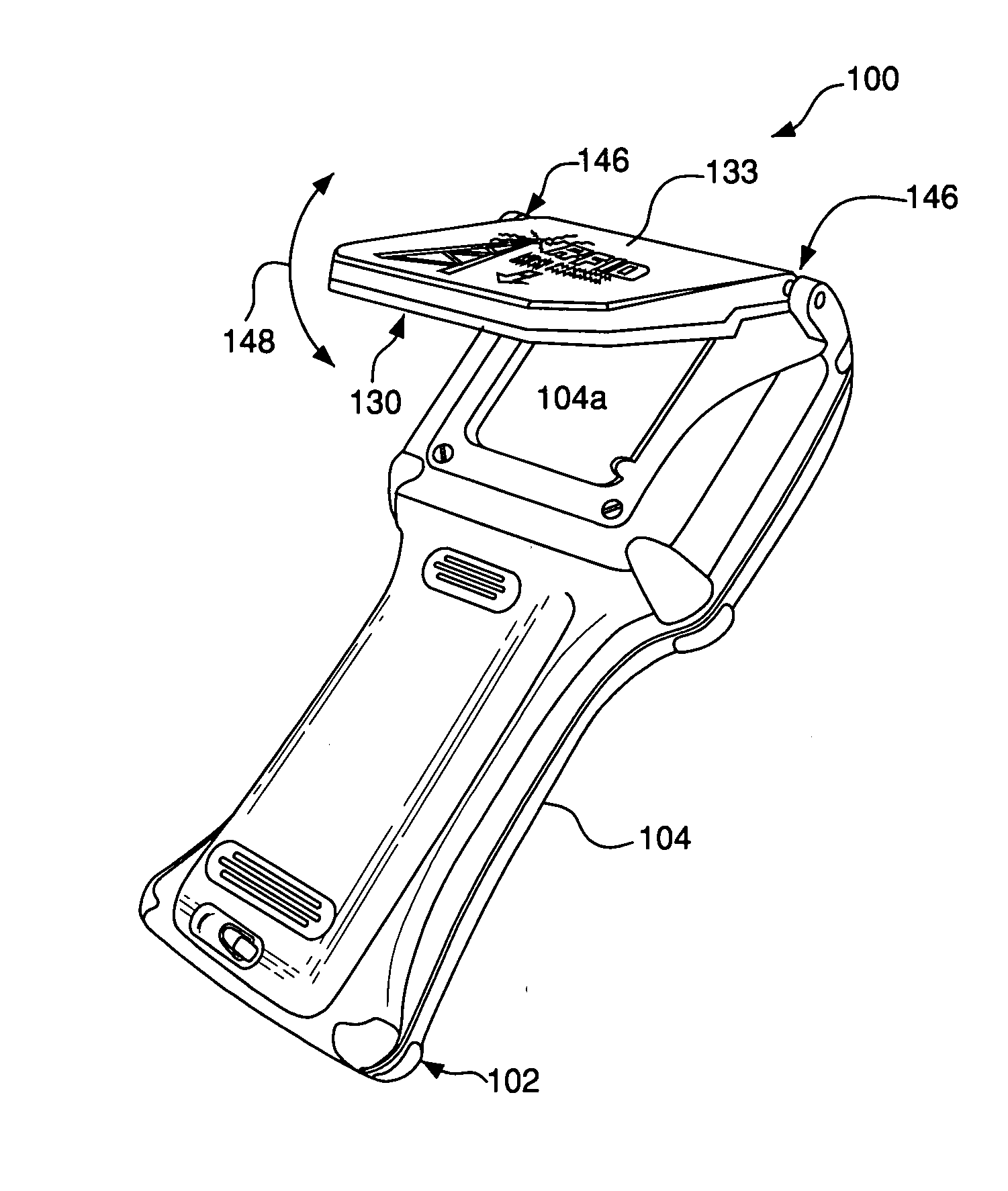
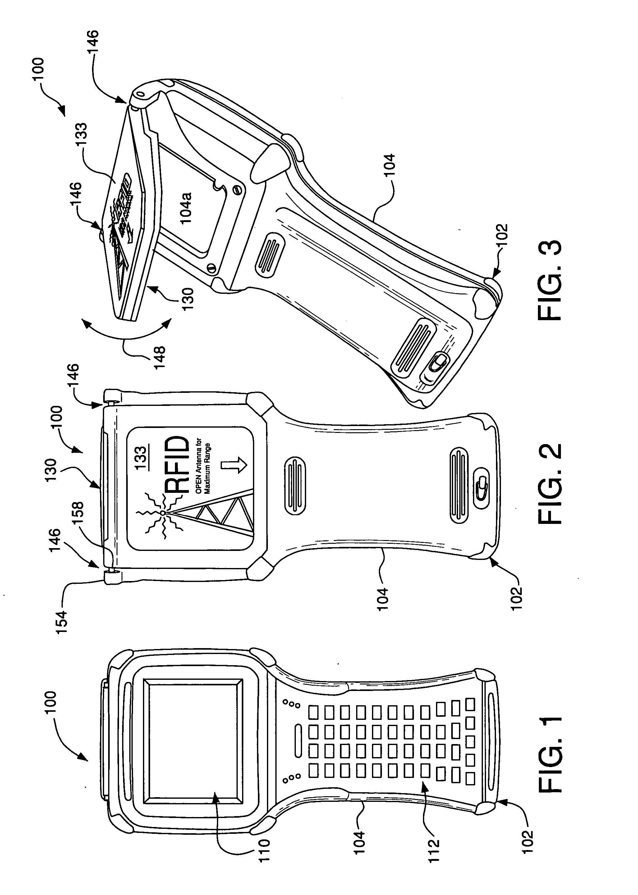
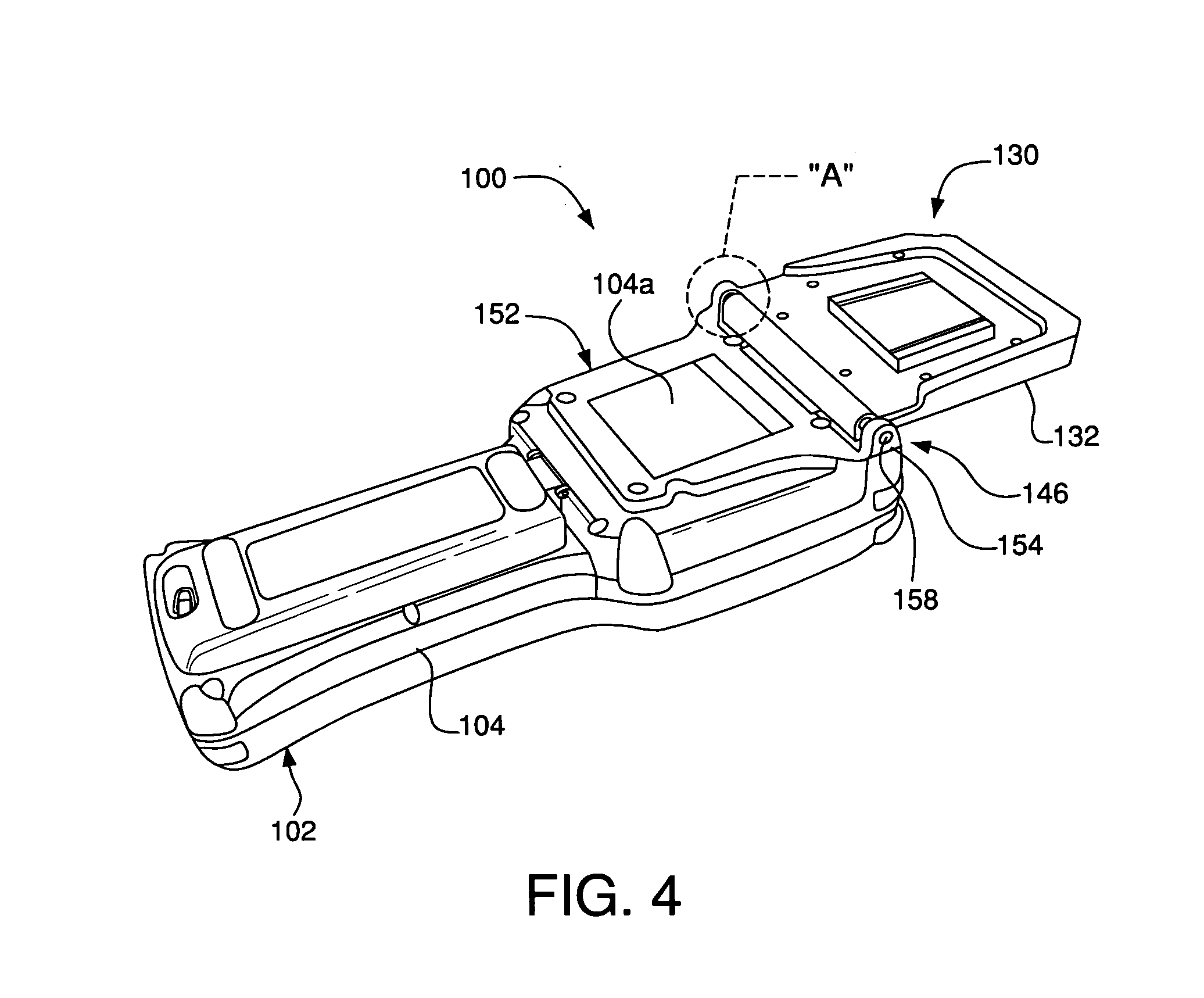
[0036] FIGS. 1 to 8, 11A, and 11B depict a preferred embodiment of an RFID reader 100. The reader 100 comprises a body 102. The body 102 includes a casing 104. The casing 104 preferably has the relatively thin, elongated portion that can act as a handle by which the user can grasp and hold the reader 100.

[0037] The body 102 includes a controller 108, a display 110, and a keypad 112 housed within the casing 102 (see FIGS. 1 and 6). The controller 108 comprises a processor such as a microprocessor 114 (see FIG. 6). The controller 108 also includes a memory-storage device 116 communicatively coupled to the microprocessor 114, and a set of computer-executable instructions 118 stored on the memory-storage device 116.

[0038] The display 110 and the keypad 112 are communicatively coupled to the processor 108. The keypad 112 preferably is located on the relatively thin (handle) portion of the casing 104, and facilitates entry of commands, data, and other inputs by the user. The display 110...


PUM


Abstract

A preferred embodiment of a hand-held radio frequency identification reader includes a first casing suitable for being grasped by a user, a second casing, and a transceiver housed within one of the first and second casings. The reader also includes an antenna housed within the second casing and communicatively coupled to the transceiver for communicatively coupling the reader to a radio frequency identification tag. The second casing is movably coupled to the first casing so that the second casing can be aligned with the radio frequency identification tag to substantially maximize a read distance of the reader while the first casing is held in a substantially fixed position in relation to the radio frequency identification tag.

Description

CROSS-REFERENCE TO RELATED APPLICATIONS [0001] This application claims priority under 35 U.S.C. § 119(e) to U.S. provisional application No. 60 / 536,965, filed Jan. 16, 2004, the contents of which is incorporated by reference herein in its entirety.FIELD OF THE INVENTION [0002] The present invention relates to radio frequency identification (RFID) systems, and more particularly, to an antenna for an RFID device such as an RFID reader. BACKGROUND OF THE INVENTION [0003] RFID systems are currently used in a variety of applications such as inventory control, theft prevention, access control, etc. RFID systems typically comprise a reader (also referred to as a tag reader or an interrogator) and a tag (also referred to as a transponder). [0004] An RFID tag for use in an inductively coupled RFID system can comprise an integrated circuit (IC) that includes modulation circuitry and non-volatile memory. The tag also comprises an antenna, often referred to as an antenna / coil. RFID tags can be ...

Claims


Application Information

Patent Timeline
IPC IPC(8): G06K7/08G06K7/10H01Q1/22H01Q1/38H01Q7/00
CPCG06K7/10336G06K7/10346H01Q7/00H01Q1/2216H01Q1/38G06K7/10881
Inventor YOUNG, DAVID H.MICK, ROGER WAYNETURCO, VINCENT A. JR.WALSH, MICHAEL FRANCIS
Owner TWO TECH
Why Eureka
Try Eureka