Descaling nozzle

a technology of scaling nozzle and nozzle head, which is applied in the direction of manufacturing tools, combustion types, lighting and heating apparatus, etc., can solve the problems of difficult to remove scale efficiently, reduce the product value, and form cracks on the surface of rolled steel, so as to improve the scaling efficiency

Active Publication Date: 2005-07-21
KYORITSU GOKIN +1
View PDF7 Cites 61 Cited by
  • Summary
  • Abstract
  • Description
  • Claims
  • Application Information

AI Technical Summary

Benefits of technology

[0017] The inventors of the present invention made intensive studies to achieve the above objects and finally found that by forming a nozzle orifice extending from a discharge orifice which is opened at a concave surface of a front end, as a specific conical tapered manner, the descaling efficiency can be improved remarkably even at a low pressure and / or a low flow rate. The present invention has been accomplished based on the above findings.

Problems solved by technology

Due to the heating in the above-mentioned heating furnace, scale comprising iron oxide forms on the surface of the steel slab, and if hot rolling is performed without removing this scale, scale cracks are formed on the surface of the rolled steel and lower the product value.
However, according to these nozzles, water should be jetted with a high pressure and it is difficult to remove scale efficiently with a low pressure or a low flow rate.
However, with the above-described descaling nozzle and descaling method, it is required to discharge water at a high pressure and a high flow rate in order to make the erosion amount large.
Furthermore, since the inner diameter of the enlarged passage is large with respect to the discharge orifice, the nozzle size becomes large.
Further, since two conical flow paths are formed, the nozzle has a complicated structure essentially.
Furthermore, it is especially difficult to prepare a nozzle tip having two conical flow paths from cemented carbide.

Method used


Image

  • Descaling nozzle
  • Descaling nozzle
  • Descaling nozzle

Examples


examples

[0076] Though this invention shall now be described based on examples, this invention is not limited by these examples.

examples 1 to 3

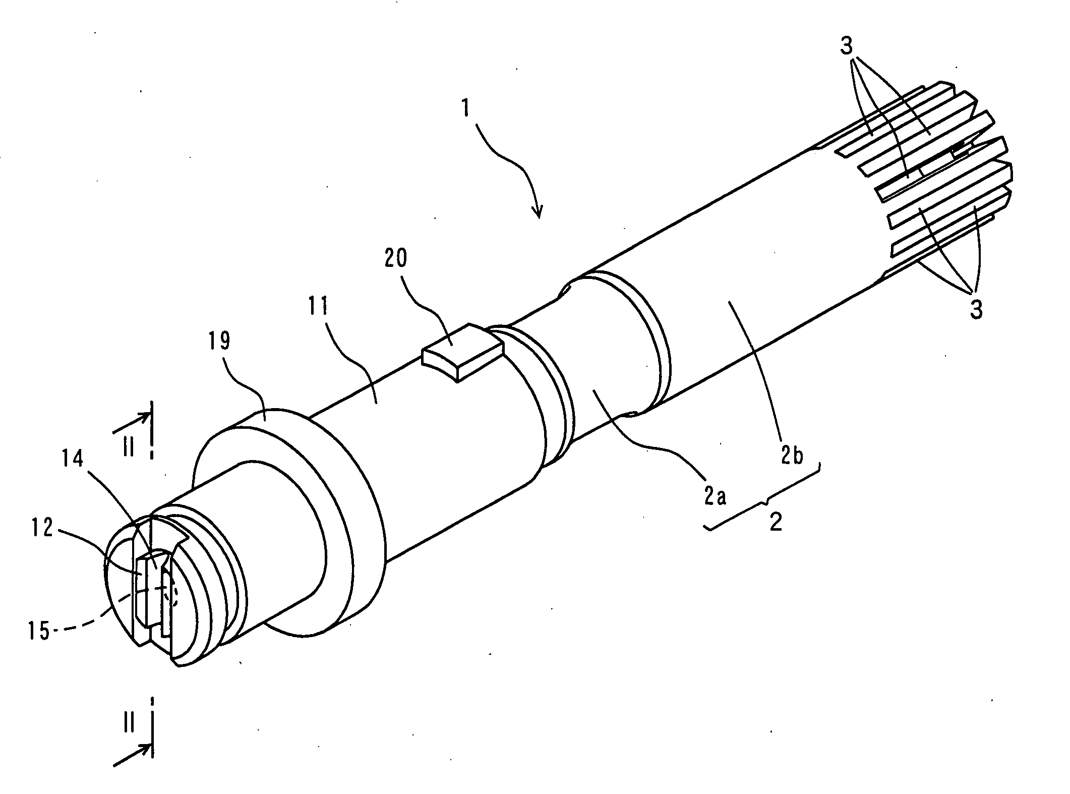
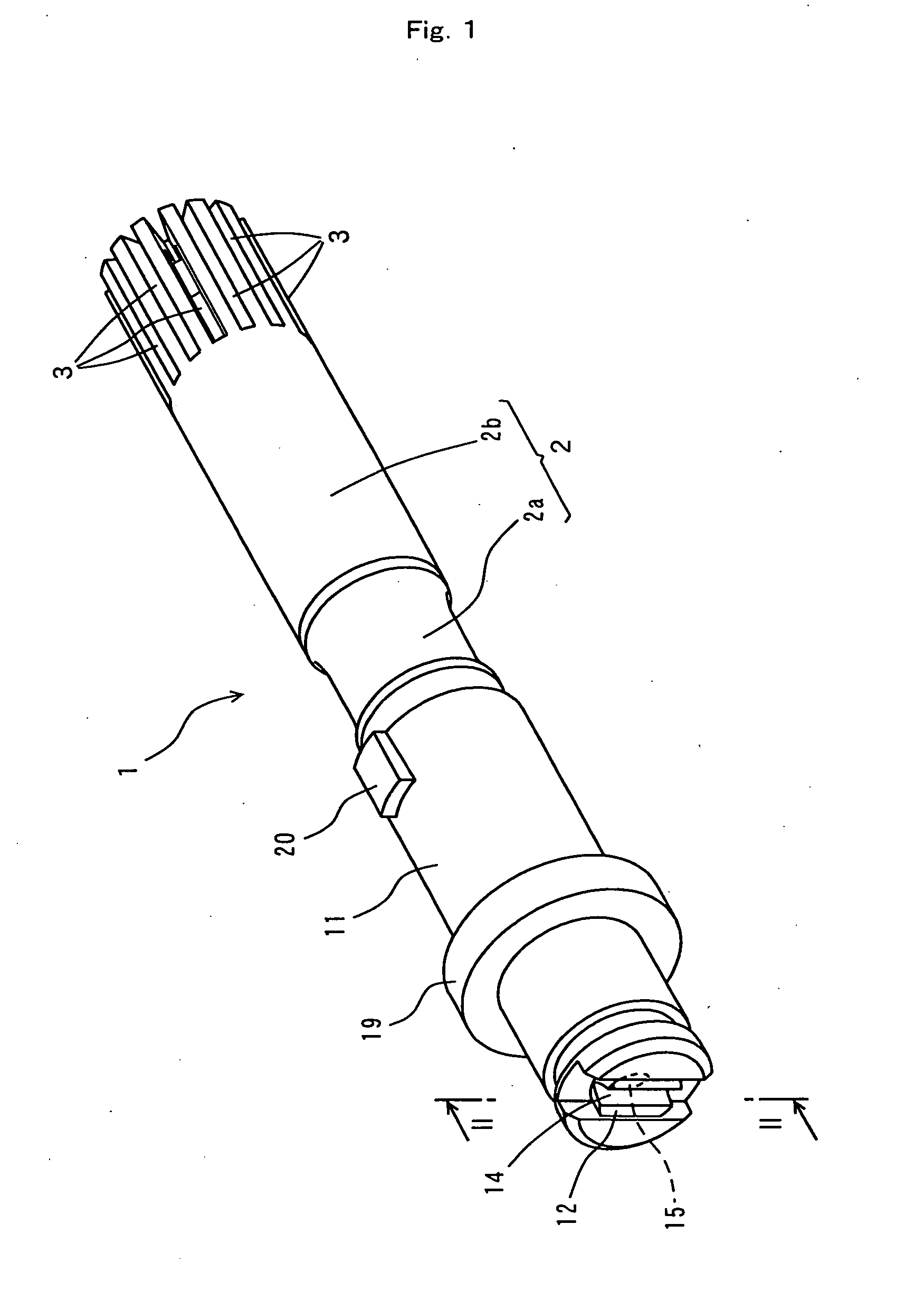
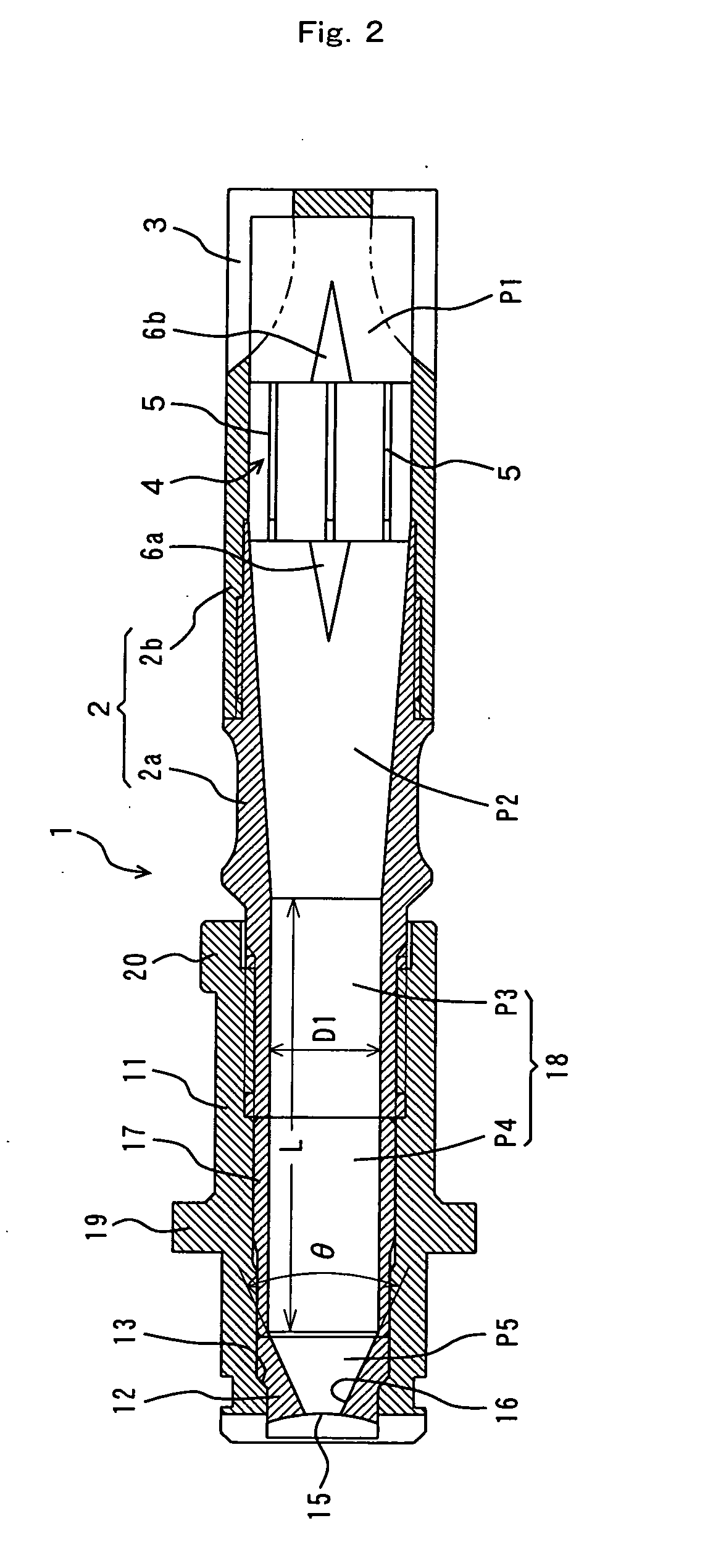
[0077] For spraying, the spray nozzle shown in FIG. 2 was used. This nozzle had a discharge orifice (having an elliptical shape with a major diameter of 3.78 mm, a minor diameter of 2.31 mm and the ratio of major diameter / minor diameter=1.6) in the nozzle tip; a tapered segment with a taper angle θ=50°, a cylindrical flow path (large-diameter segment) with an inner diameter of φ11 mm and a length of 43.4 mm that extended to a nozzle case and a middle part of a first casing; an inclined segment (inclined flow path) (length: 36.1 mm) extending with a taper angle of 7.5° from the upstream end of the cylindrical flow path (large diameter segment); a cylindrical flow path with an inner diameter of φ16 mm extending from the upstream end of the inclined flow path and having a stabilizer (length in axial direction of the blades: 16 mm; eight blades extending radially from the axis part) fitted therein; and a plurality of slits formed at an upstream end of the second casing. The ratio (D1 / D2...


PUM

PropertyMeasurementUnit
taper angleaaaaaaaaaa
pressureaaaaaaaaaa

Abstract

A nozzle orifice of a nozzle 1 comprises a tapered segment 16 extending from an elliptical discharge orifice 15 and having a taper angle θ of 30 to 80°, and a large-diameter segment 18 continuing with the tapered segment, and scale on a steel plate is removed by discharging water from the nozzle at a distance between discharge orifice 15 and the steel plate of not more than 600 mm, a pressure of 5 to 30 MPa, and a discharge flow rate of 40 to 200 l/minute. The ratio of the inner diameter of large-diameter segment 18 relative to the minor diameter of the discharge orifice 15 is not less than 3 and less than 7. Also, the discharge flow from the nozzle spreads in a single direction (width direction) within a plane perpendicular to the central axis of the nozzle and the erosion thickness angle is 1.5 to 30 in the direction (thickness direction) perpendicular to the width direction. Such a descaling nozzle enables that scale is removed efficiently at low pressure and/or low flow rate while restraining the cooling of a steel plate.

Description

TECHNICAL FIELD [0001] The present invention relates to a descaling nozzle for removing scale from a surface of a rolled steel manufactured by hot rolling and a cemented carbide nozzle tip which is useful for this nozzle. BACKGROUND ART [0002] A hot rolled steel is manufactured by heating a steel slab to about 1100 to 1400° C. in a heating furnace under an oxidizing atmosphere and hot rolling the heated slab by a rolling mill. Due to the heating in the above-mentioned heating furnace, scale comprising iron oxide forms on the surface of the steel slab, and if hot rolling is performed without removing this scale, scale cracks are formed on the surface of the rolled steel and lower the product value. Descaling nozzles have been proposed for removing such scale by a high-pressure jet of water. [0003] Japanese Patent Application Laid-Open No. 24937 / 1996 (JP-8-24937A) discloses a steel plate surface cleaning method in which the surface temperature of a steel plate is heated to not lower t...

Claims


Application Information

Patent Timeline
Patent Type & Authority Applications(United States)
IPC IPC(8): B05B1/04B05B15/00B05B15/40B21B45/08
CPCB05B1/042B21B45/08B05B15/008B05B1/34B05B15/40B05B1/3402B05B1/04
Inventor TANIGAKI, AKIHIKONISHIYAMA, TAKASHIKARUBE, KENTAANDACHI, KAZUNARI
Owner KYORITSU GOKIN
Why Eureka
Try Eureka