Crystal-based coincidence timing calibration method

a crystal-based coincidence timing and calibration method technology, applied in the field of positron emission tomography, can solve the problem of still existing timing variations amongst patients

Inactive Publication Date: 2005-07-21
GENERAL ELECTRIC CO
View PDF10 Cites 8 Cited by
  • Summary
  • Abstract
  • Description
  • Claims
  • Application Information

AI Technical Summary

Problems solved by technology

This method is described in U.S. Pat. No. 5,272,344, entitled “Automated Coincidence Timing Calibration For A PET Scanner.” However, timing variations still exist among the crystals within each detector, owing to various factors, including non-uniformity of the PMT cathode response, and different electronic circuits and components through which signals coming from different anodes pass.

Method used


Image

  • Crystal-based coincidence timing calibration method
  • Crystal-based coincidence timing calibration method
  • Crystal-based coincidence timing calibration method

Examples


Embodiment Construction

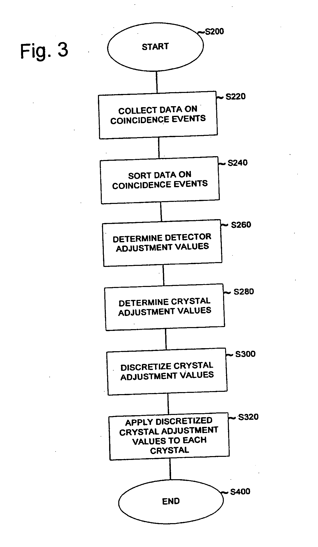
[0021] A method of calibrating detectors in a detector ring of a PET scanner, each detector including a plurality of crystals, the PET scanner having a field of view, is disclosed. The method comprises collecting timing data indicative of coincidence events occurring between each pair of crystals within the field of view. The method further comprises determining a detector adjustment value for each detector, determining a crystal adjustment value for each crystal in each detector, and discretizing the crystal adjustment value for each crystal to produce a discretized crystal adjustment value for each crystal. Lastly, the method comprises calibrating each detector by applying the discretized crystal adjustment value for each crystal in each detector to the collected timing data indicative of coincidence events.

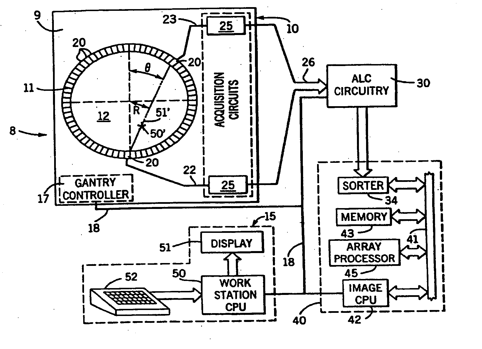
[0022]FIG. 1 is a schematic view of a PET system in accordance with one embodiment of the invention. As shown in FIG. 1, PET imaging system 8 includes an acquisition system 10...


PUM


Abstract

A method of calibrating detectors in a detector ring of a PET scanner, each detector including a plurality of crystals, the PET scanner having a field of view, is disclosed. The method comprises collecting timing data indicative of coincidence events occurring between each pair of crystals within the field of view. The method further comprises determining a detector adjustment value for each detector, determining a crystal adjustment value for each crystal in each detector, and discretizing the crystal adjustment value for each crystal to produce a discretized crystal adjustment value for each crystal. Lastly, the method comprises calibrating each detector by applying the discretized crystal adjustment value for each crystal in each detector to the collected timing data indicative of coincidence events.

Description

[0001] This application is a continuation of U.S. patent application Ser. No. 10 / 284,800 filed Oct. 31, 2002, entitled “Crystal-Based Coincidence Timing Calibration Method,” the contents of which are incorporated herein in their entirety to the extent that it is consistent with this invention and application.BACKGROUND OF THE INVENTION [0002] The invention relates generally to positron emission tomography (PET) and more particularly to the coincidence timing calibration of PET systems. [0003] Positrons are antimatter electrons which are emitted by radionuclides that have been prepared using a cyclotron or other device. The radionuclides are employed as radioactive tracers called “radiopharmaceuticals” by incorporating them into substances which are introduced into the patient and become involved in such processes as glucose metabolism, fatty acid metabolism and protein synthesis. [0004] As the radionuclides decay, they emit positrons. The positrons travel a very short distance befor...

Claims


Application Information

Patent Timeline
Patent Type & Authority Applications(United States)
IPC IPC(8): G01T1/164G01T1/161G01T1/172G01T1/29
CPCG01T1/2985
Inventor WILLIAMS, JOHN J.LUO, DERSHANLIMKEMAN, MARK K.COOK, MICHAEL J.MCDANIEL, DAVID L.OSWALT, EDWIN L.FEILEN, MARK P.
Owner GENERAL ELECTRIC CO
Why Eureka
Try Eureka