Inverter with two switching stages for driving lamp
- Summary
- Abstract
- Description
- Claims
- Application Information
AI Technical Summary
Benefits of technology
Problems solved by technology
Method used
Image
Examples
Embodiment Construction
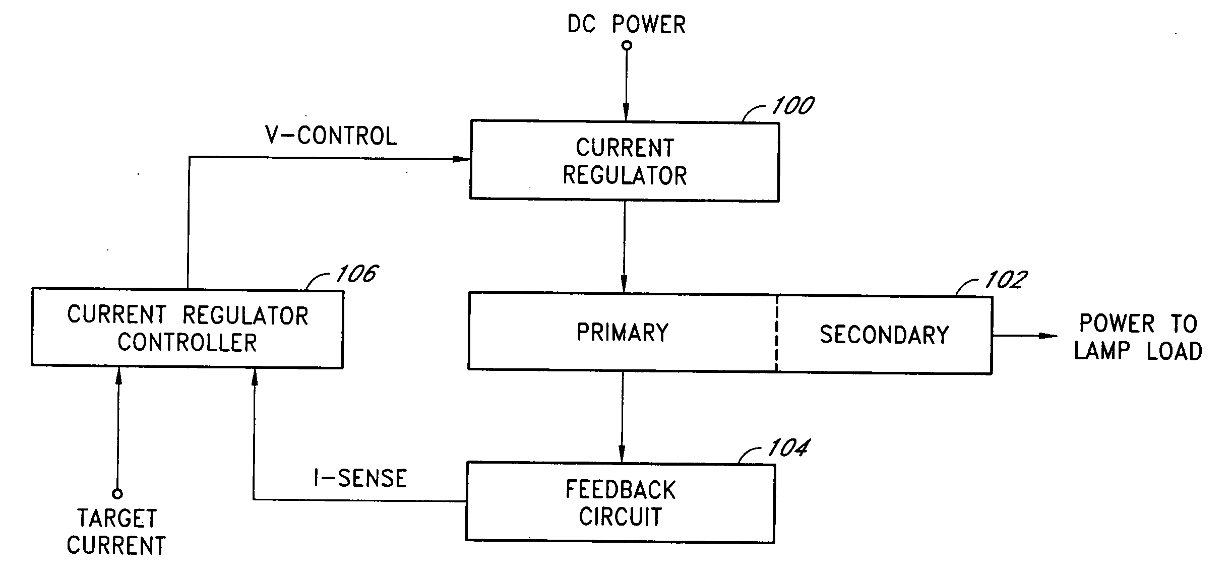
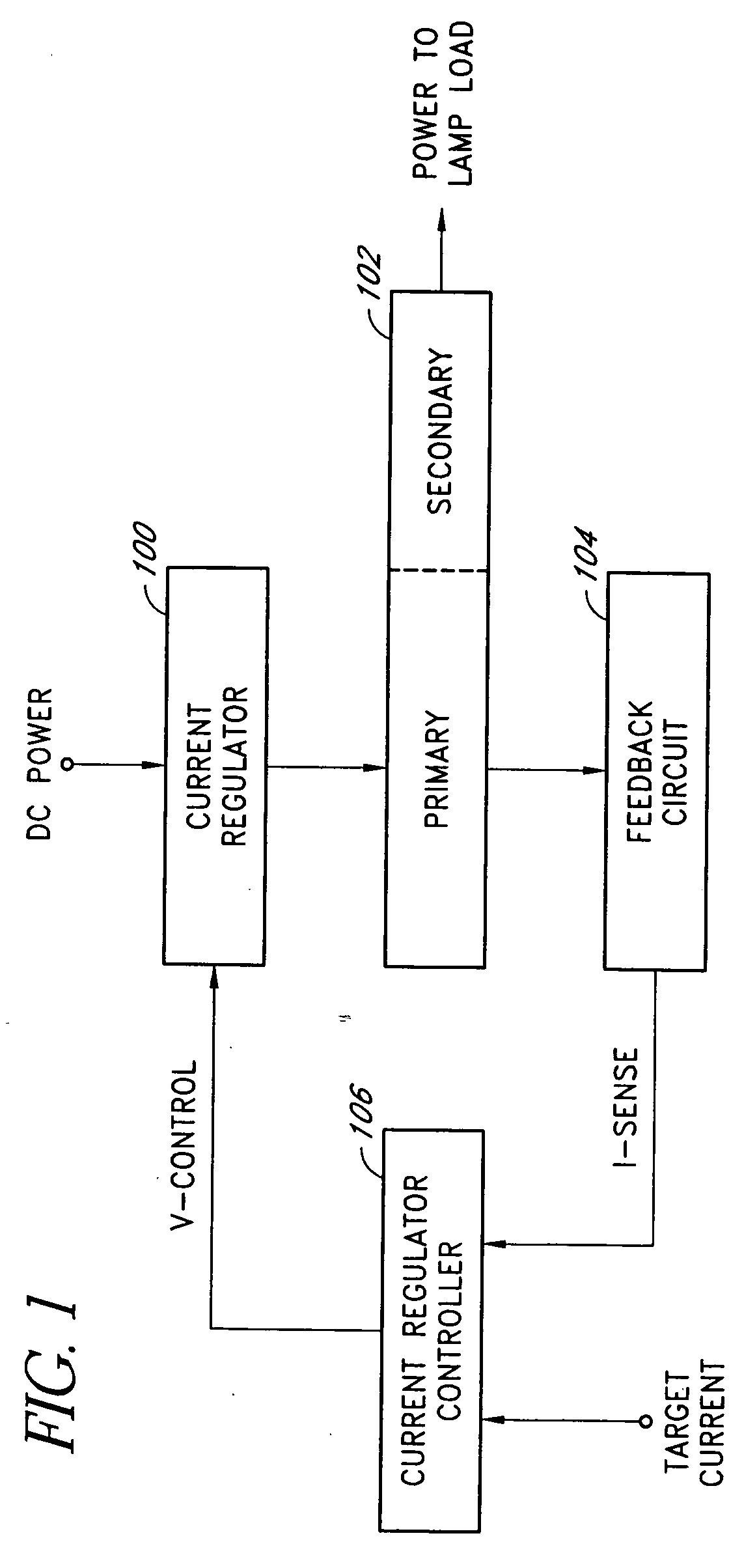
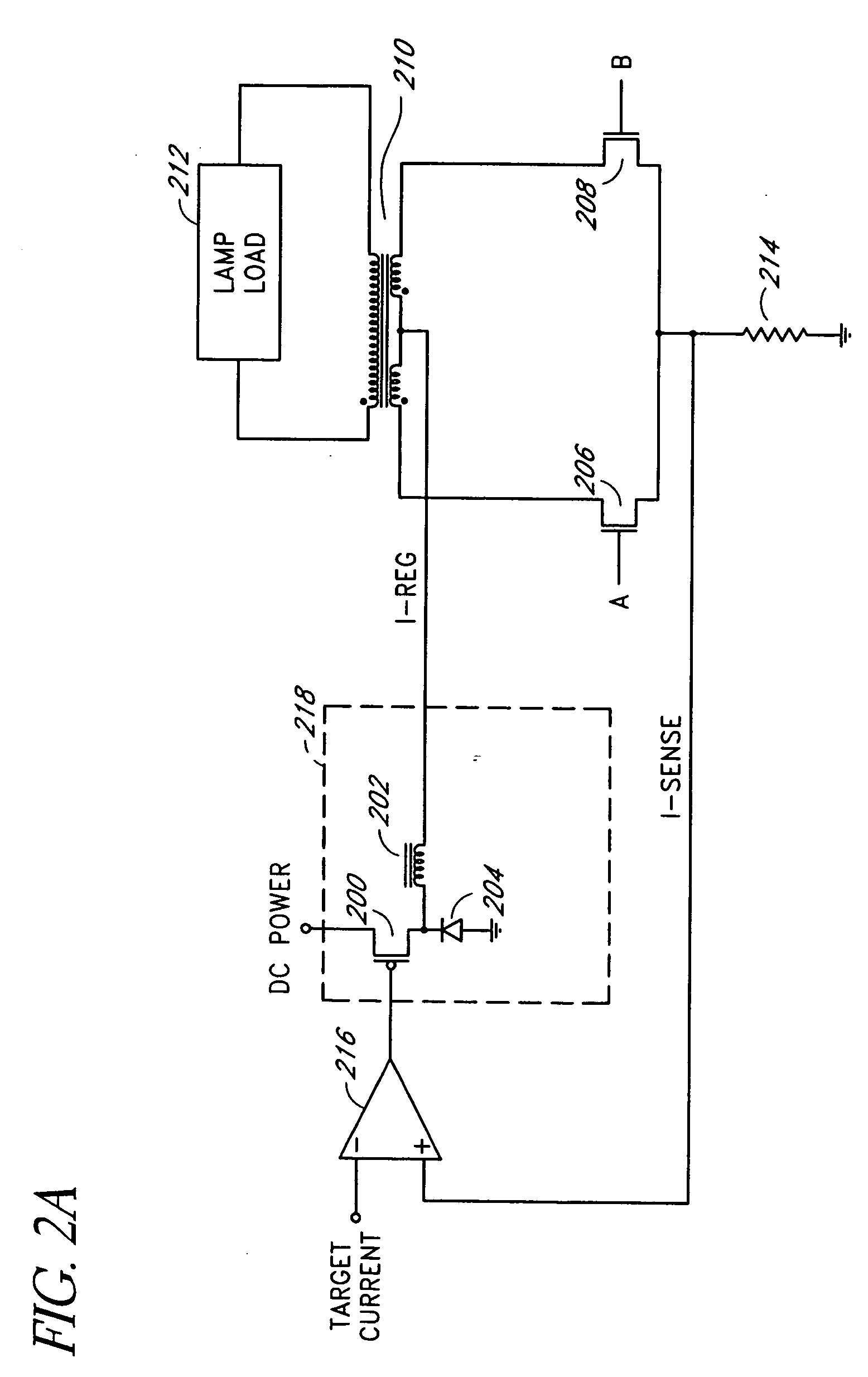
[0028] Embodiments of the present invention will be described hereinafter with reference to the drawings. FIG. 1 is a simplified block diagram of one embodiment of a current-mode inverter. The current-mode inverter includes an input current regulator 100, a polarity-switching and transformer network (or polarity reversing stage) 102, a feedback circuit 104, and a current regulator controller 106. The input current regulator 100 accepts a DC power source (e.g., a regulated or unregulated DC voltage) and generates a regulated current for the polarity-switching and transformer network 102. The polarity-switching and transformer network 102 includes semiconductor switches, such as metal-oxide-semiconductor field-effect-transistors (MOSFETs), directly coupled to a primary winding of a closely-coupled transformer. The semiconductor switches are controlled by a controller (e.g., a pulse width modulator) to periodically couple the regulated current through the primary winding in alternate s...
PUM
 Abstract
Description
Claims
Application Information
 - R&D
- Intellectual Property
- Life Sciences
- Materials
- Tech Scout
- Unparalleled Data Quality
- Higher Quality Content
- 60% Fewer Hallucinations
Browse by: Latest US Patents, China's latest patents, Technical Efficacy Thesaurus, Application Domain, Technology Topic, Popular Technical Reports.
© 2025 PatSnap. All rights reserved.Legal|Privacy policy|Modern Slavery Act Transparency Statement|Sitemap|About US| Contact US: help@patsnap.com


