
Class-D amplifier

a class-d amplifier and amplifier technology, applied in amplifiers, amplifiers with semiconductor devices/discharge tubes, negative-feedback circuit arrangements, etc., can solve the problems of large loss, large distortion of output signals, large cost increase, etc., and achieve low distortion and small power loss

Active Publication Date: 2005-07-21
YAMAHA CORP
View PDF5 Cites 29 Cited by
  • Summary
  • Abstract
  • Description
  • Claims
  • Application Information

AI Technical Summary

Benefits of technology

[0008] The present invention has been made to solve the above-described problems, and therefore, is to provide a class-D amplifier operable in low distortion and under small power loss.
[0010] Also, the present invention is to provide a class-D amplifier capable of reducing a DC voltage component in an output thereof to substantially zero volt.
[0071] In accordance with the present invention, the class-D amplifier can be provided which is operable in low distortion and under small power loss.
[0072] Also, the present invention can provide the class-D amplifier operable in low distortion and under small power loss, while the transformer is not employed, and also, the DC voltage component in the output thereof can be reduced to substantially zero volt.

Problems solved by technology

As a result, in the conventional class-D amplifier, even in such a case that the input signal is not present, the current may flow through the low-pass filter, which cause the large loss.
However, the conventional pulse width modulating amplifier described in the above-explained patent publication 1 owns such a problem that the transformer is required so as to convert the impedance and to cut off the DC voltage, which may conduct the large-scaled apparatus and the increase in cost thereof.
Sho-56-27001 has another problem that since the comparator compares the simple triangular wave with the input signal, the distortion of the output signal is large.
As a consequence, the digital amplifying circuit described in Japanese Patent Disclosure No. 2000-500625 owns a problem that since this digital amplifying circuit cannot be arranged by employing the analog circuit, the analog input signal cannot be amplified while maintaining the better linearity.
However, this circuit for compensating the output switch distortion is constituted by employing only such a digital circuit as the logic circuit, so that the conventional digital amplifying circuit cannot amplify the analog input signal under better linearity condition.

Method used


Image

  • Class-D amplifier
  • Class-D amplifier
  • Class-D amplifier

Examples


embodiment 1

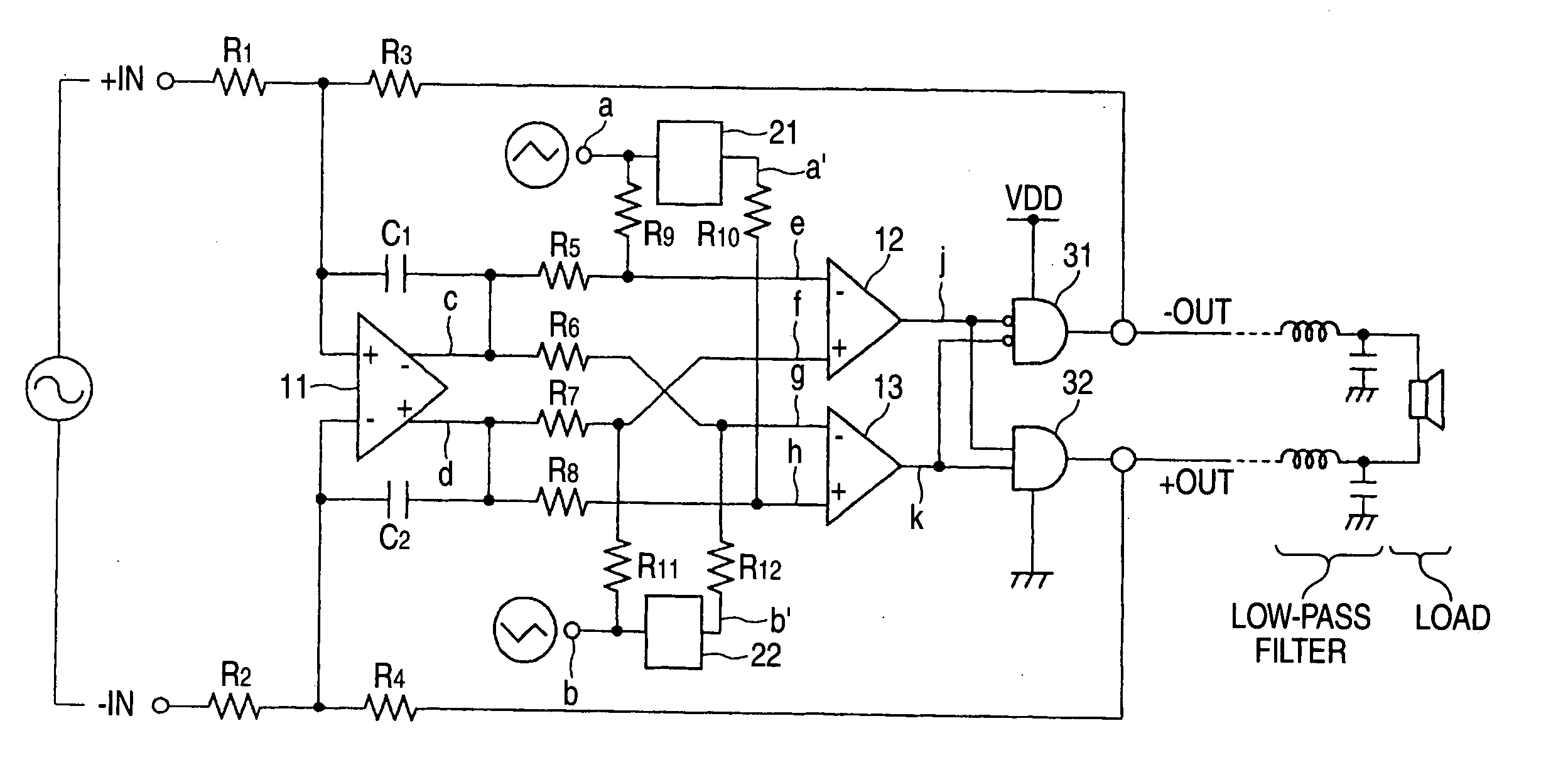
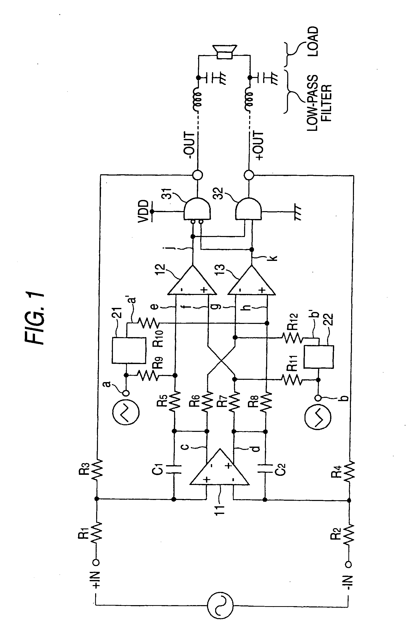
[0091]FIG. 1 is a circuit diagram for indicating a structural example of a class-D amplifier according to an embodiment 1 of the present invention.

[0092] This class-D amplifier is arranged by resistors R1, R2, R3, R4, R5, R6, R7, R8, R9, R10, R11, and R12, capacitors C1 and C2, an operational amplifier 11, comparators 12 and 13, delay circuits 21 and 22, an AND circuit (low active) 31, and another AND circuit 32. Predetermined triangular wave signals “a” and “b” are applied to one terminals of the resistors R9 and R11 respectively in this drawing. Both the triangular wave signal “a” and the triangular wave signal “b” are such signals having the same waveforms, the phases of which are different from each other by 180 degrees.

[0093] One terminals of the resistors R1 and R2 constitute differential input terminals of analog input signals, respectively. Then, one terminal of the resistor R1 constitutes a plus-sided input terminal (+ IN), and one terminal of the resistor R2 constitutes ...

embodiment 2

[0122] Next, an embodiment 2 of the present invention will now be described with reference to FIG. 5. FIG. 5 is a circuit diagram for indicating a structural example of a class-D amplifier according to the embodiment 2 of the present invention. This class-D amplifier is arranged by resistors R51, R52, R53, R54, R55, and R56, a capacitor C51, operational amplifiers 61 and 64, comparators 62 and 63, an AND circuit (low active) 71, and another AND circuit 72. A triangular wave signal “a” is applied to a plus-sided input terminal of the comparator 62, another triangular wave signal “b′” is applied to a plus-sided input terminal of the comparator 63.

[0123] The triangular wave signal “b′” corresponds to such a triangular wave signal which is produced by that a phase of a triangular wave signal “b” obtained by inverting the triangular wave signal “a” (namely, phase is delayed by the 180 degrees) is further delayed by a very small angle “θ”. As a result, both the triangular wave signal “a”...

embodiment 3

[0135] Next, an embodiment 3 of the present invention will now be described with reference to FIG. 8 to FIG. 11. FIG. 8 is a circuit diagram for representing a structural example of a class-D amplifier according to the embodiment 3 of the present invention. Different from the class-D amplifier according to the embodiment 1, in this class-D amplifier, the delay circuits 21 and 22 are not employed as the structural elements. In this class D amplifier, a triangular wave signal “a” is applied to one terminal of a resistor R10, whereas another triangular wave signal “b” is applied to one terminal of another resistor R12. Structural circuit arrangement other than the above-described circuit arrangement in the class-D amplifier shown in FIG. 8 are similar to those of the class-D amplifier according to the embodiment 1 shown in FIG. 1. It should be understood that respective resistance values of resistors R5, R6, R7, R8, R9, R10, R11, and R12, which constitute a synthesizing circuit in this...


PUM


Abstract

A class-D amplifier includes: an operational amplifier and capacitors, which constitute an integrator for integrating a difference between a plus-sided input signal and a minus-sided input signal which constitute analog input signals; delay circuits for delaying a phase of a triangular wave by a desirable very small angle; resistors, which constitute a synthesizing circuit for synthesizing an output of the integrator, the triangular wave, and outputs of the delay circuits with each other; comparators for comparing outputs of the synthesizing circuit with each other; AND circuits which constitute a buffer for inputting outputs of the comparators; and resistors feeding back an output of the buffer to an input side of the integrator.

Description

BACKGROUND OF THE INVENTION [0001] The present invention is related to a class-D amplifier. [0002] Class-D amplifiers perform power amplification by pulse-width-modulating (PWM) input signals, and are utilized so as to perform power amplifications of audio signals. As conventional class-D amplifiers, there is such a class-D amplifier which is arranged by an integrator for integrating an analog input signal, a comparator for comparing an output signal of the integrator with a predetermined triangular wave, and a buffer (pulse amplifier) for amplifying an output signal of the comparator to output a pulse signal. In this conventional class-D amplifier, the pulse signal output from the buffer is fed back to the input side of the integrator. Then, the output signal of the buffer is filtered by a low-pass filter constructed of a coil and a capacitor so as to obtain an analog signal which drives a load such as a speaker. [0003] As conventional pulse width modulating amplifiers, there is su...

Claims


Application Information

Patent Timeline
Patent Type & Authority Applications(United States)
IPC IPC(8): H03F1/34H03F99/00H03F3/217
CPCH03F1/34H03F2200/78H03F3/2173H03F3/217
Inventor MAEJIMA, TOSHIO
Owner YAMAHA CORP
Learn More