Electrode pattern for touch panels

a technology of resistive pattern and touch panel, which is applied in the direction of instruments, cathode-ray tube indicators, computing, etc., can solve the problems of low impedance and deviation of voltage lines, and achieve the effect of low impedance and low production yield

Inactive Publication Date: 2005-07-21
WINTEK CORP
View PDF2 Cites 5 Cited by
  • Summary
  • Abstract
  • Description
  • Claims
  • Application Information

AI Technical Summary

Benefits of technology

[0010] Therefore the primary object of the present invention is to solve the disadvantages of the conventional electrode pattern design such as the difficult fabrication process caused by separation and non-continuity, lower production yield, and the undesirable electrode pattern with a continuous border of four sides mentioned above. The invention provides a liner circuit for touch panels. The touch panel according to the invention includes a lower substrate, a electrode pattern layer, a dot spacer, a first insulation layer, a conductive wire layer, a second insulation layer, and an upper substrate. The feature of the invention is that the continuous electrode pattern layer is a rectangular circuit with continuous four sides. The electrode pattern on each side has two ends formed respectively a straight line rather than a curve directing inwards so that the phenomenon of the voltage line deviation caused by over-correction and the too low impedance is improved. The middle portion of each side of the electrode pattern forms a curve directing inwards towards a touch area. Thus the curved voltage line measured at the equidistance in parallel with the electrode pattern occurred to the conventional straight electrode pattern also is improved.

Problems solved by technology

But the corners are over-corrected and result in a lower impedance and a deviation of the voltage line 22.

Method used


Image

  • Electrode pattern for touch panels
  • Electrode pattern for touch panels
  • Electrode pattern for touch panels

Examples


Embodiment Construction

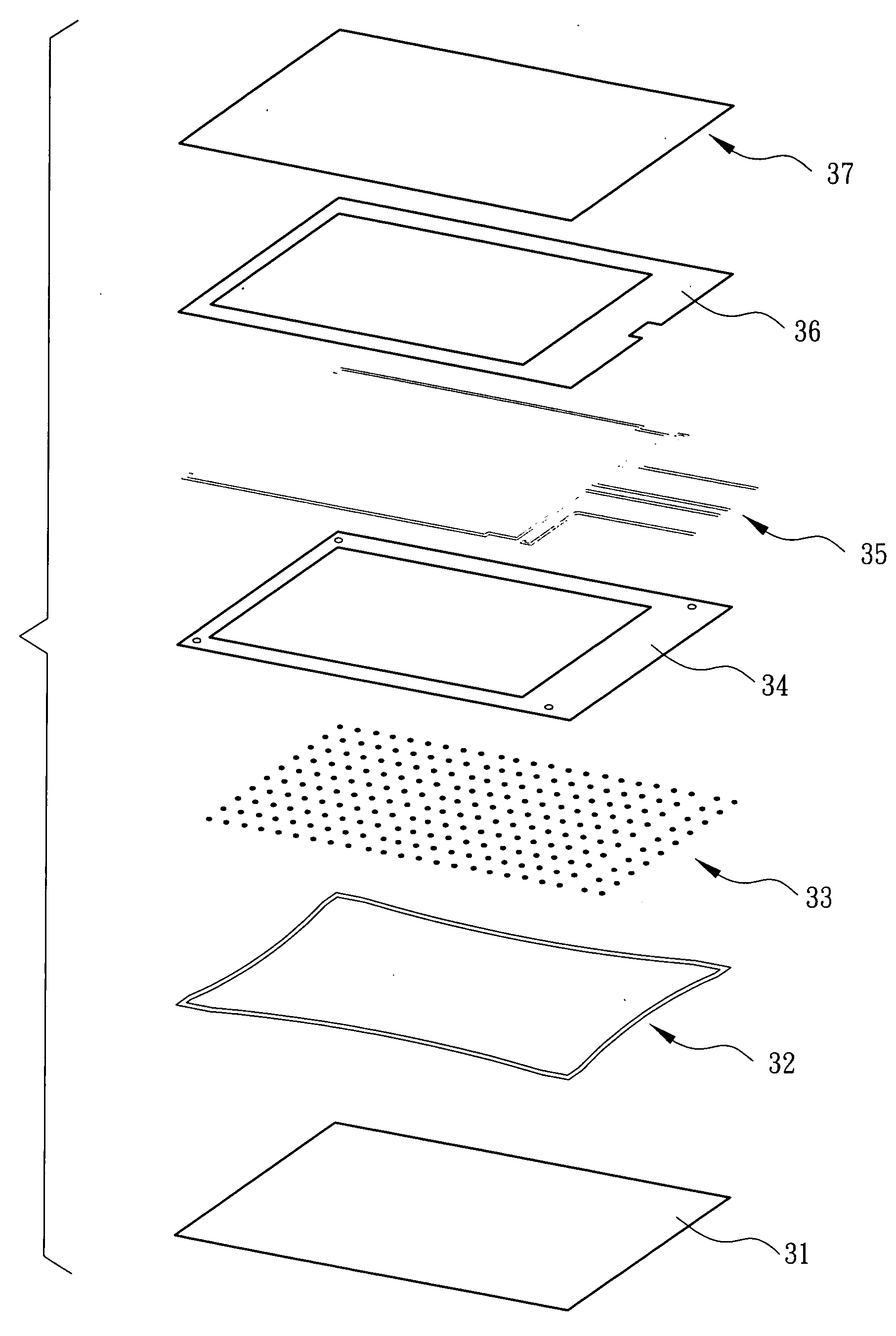
[0017] Refer to FIG. 3 for an exploded view of a touch panel according to the invention. The invention aims to provide a electrode pattern for a touch panel. The touch panel includes, from bottom to top in this order, a lower substrate 31, a dot spacer 33, a electrode pattern layer 32, a first insulation layer 34, a conductive wire layer 35, a second insulation layer 36, and an upper substrate 37.

[0018] The lower substrate 31 may be formed by uniformly depositing ITO (Indium Tin Oxide) on a glass to form a conductive film of an uniform sheet resistance. The dot spacer 33 may be formed by printing on the lower substrate 31.

[0019] The electrode pattern layer 32 may be formed by depositing ITO (Indium Tin Oxide) on the peripheral border of the glass with a circuit pattern formed by etching, then fabricate the lower substrate 31. Another approach is to deposit chrome (Cr) on the peripheral border of the lower substrate 31, then form the circuit pattern by etching. Yet another approach...


PUM


Abstract

An electrode pattern for touch panels is continuous with a border. Each side of the border has two ends formed respectively a straight line and a middle portion formed a curve directing inwards towards a touch area. The touch area surrounded by the electrode pattern has a uniform impedance. When an external voltage is applied to the electrode pattern, a continuous potential difference altering linearly is formed such that the touch area can output an electric signal to be precisely detected by a computer.

Description

FIELD OF THE INVENTION [0001] The present invention relates to an electrode pattern to provide linear response for touch panels and particularly to an electrode pattern for five-wire resistance type touch panels. BACKGROUND OF THE INVENTION [0002] Advances of technology have made input devices of information, communication and electronic products more diversified. The touch panel is a novel and more humanized input device, thus has gained growing acceptance. The touch panel includes a glass panel consisting of a conductive glass and a conductive film. It is an input device to display required images by touch through a wire configuration and a control IC on a circuit board. [0003] As the touch panel has a humanized input interface, an item may be directly selected through a finger or a stylus according to the function shown on the picture without any instruction or learning. Its application scope is very large. The main applications include: (1) portable communication, consumer elect...

Claims


Application Information

Patent Timeline
Patent Type & Authority Applications(United States)
IPC IPC(8): G06F3/03G06F3/045G09G5/00
CPCG06F3/045
Inventor WANG, CHUN-HAOTSAI, DI-SHINGWU, CHEN-MING
Owner WINTEK CORP
Why Eureka
Try Eureka