
Method and apparatus for producing a thermoplastic resin film

a thermoplastic resin and film technology, applied in the field of thermoplastic resin film methods and apparatuses, can solve the problems of foreign matter defects, the film temperature of the anti-cooling drum-side surface cannot easily be dropped to the desired temperature, and the film is difficult to clean, so as to reduce the damage caused by foreign matter defects, reduce production yield, and reduce foreign matter damage

Active Publication Date: 2012-08-09
TORAY IND INC
View PDF2 Cites 0 Cited by
  • Summary
  • Abstract
  • Description
  • Claims
  • Application Information

AI Technical Summary

Benefits of technology

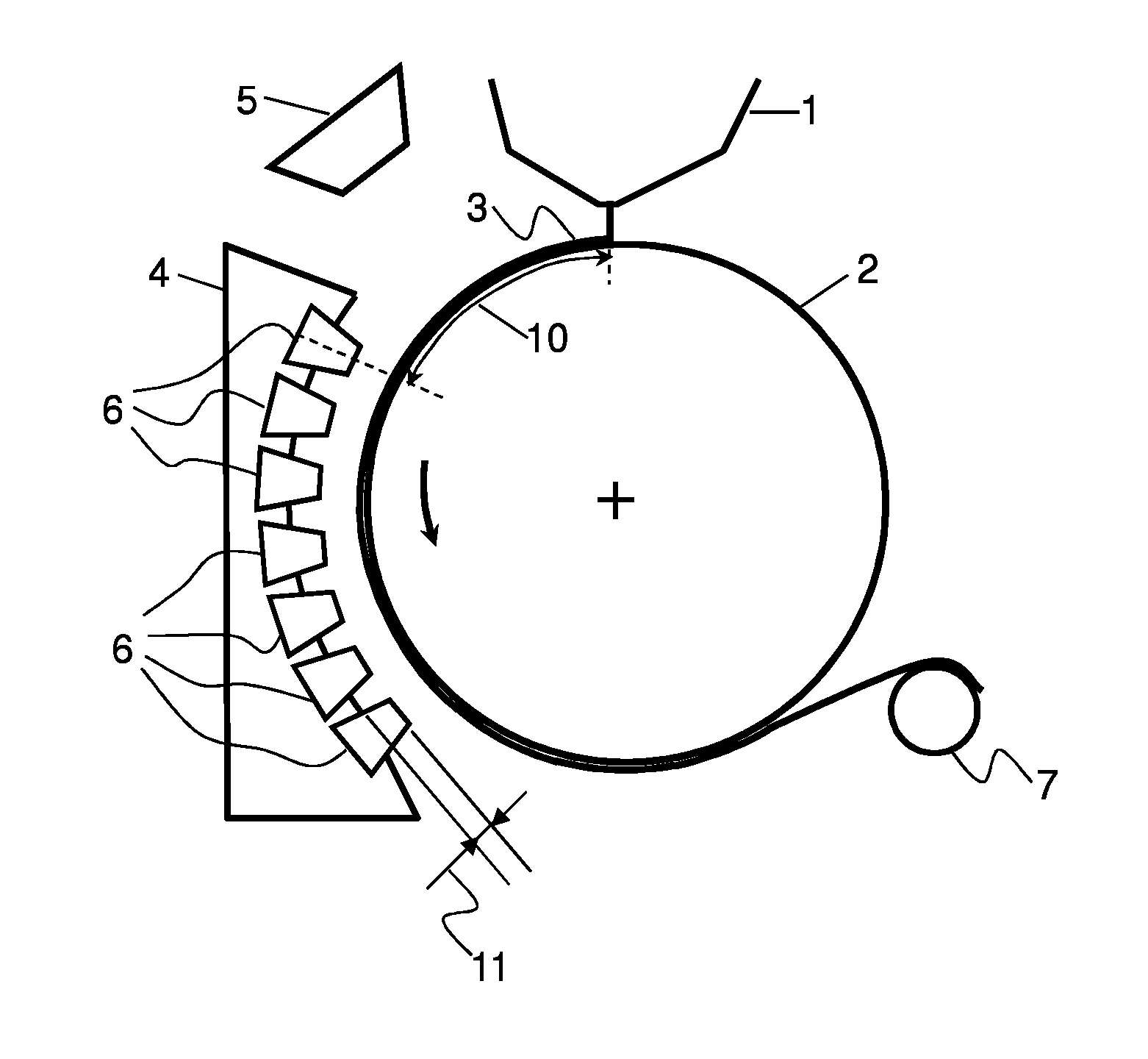
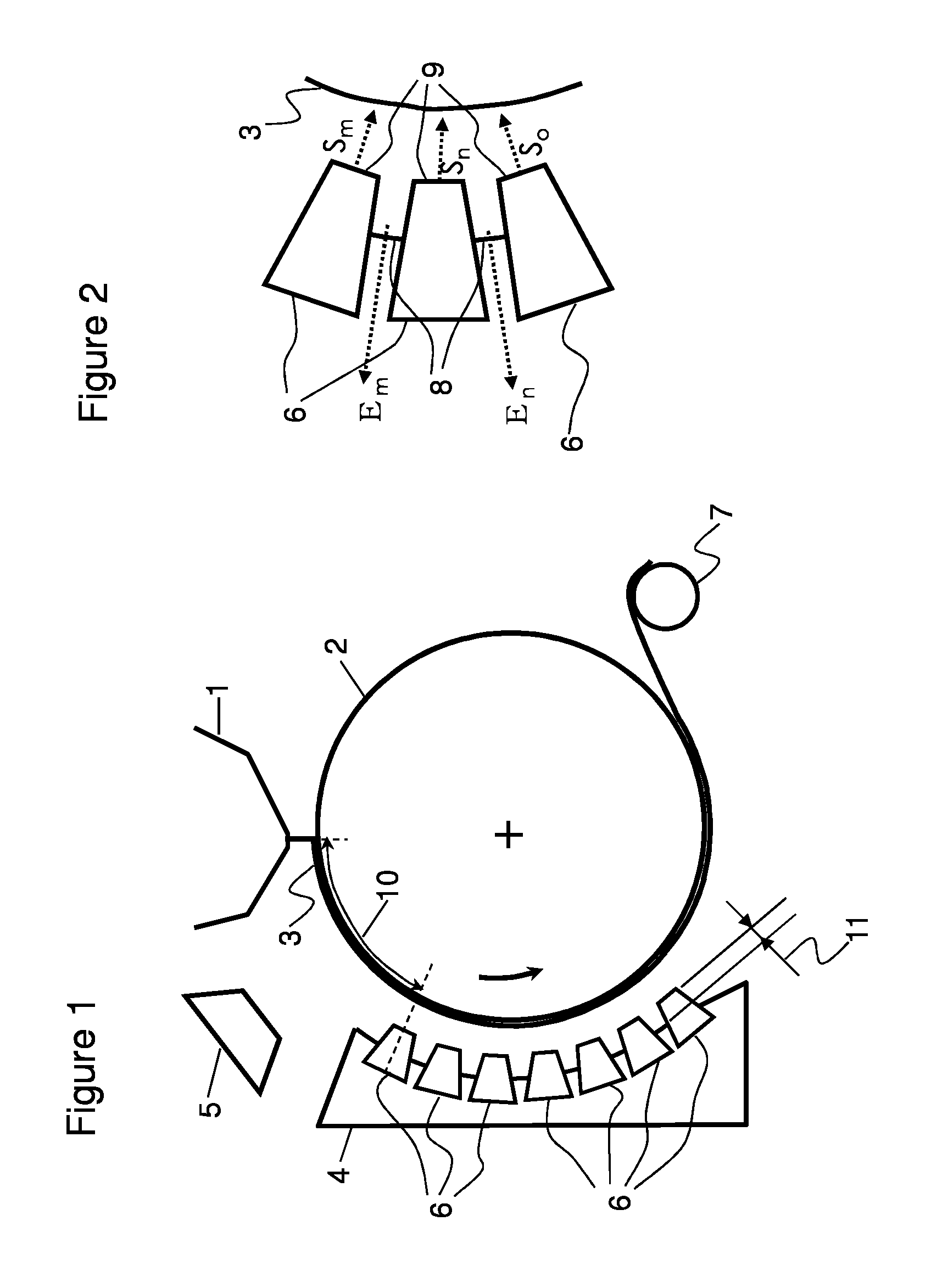
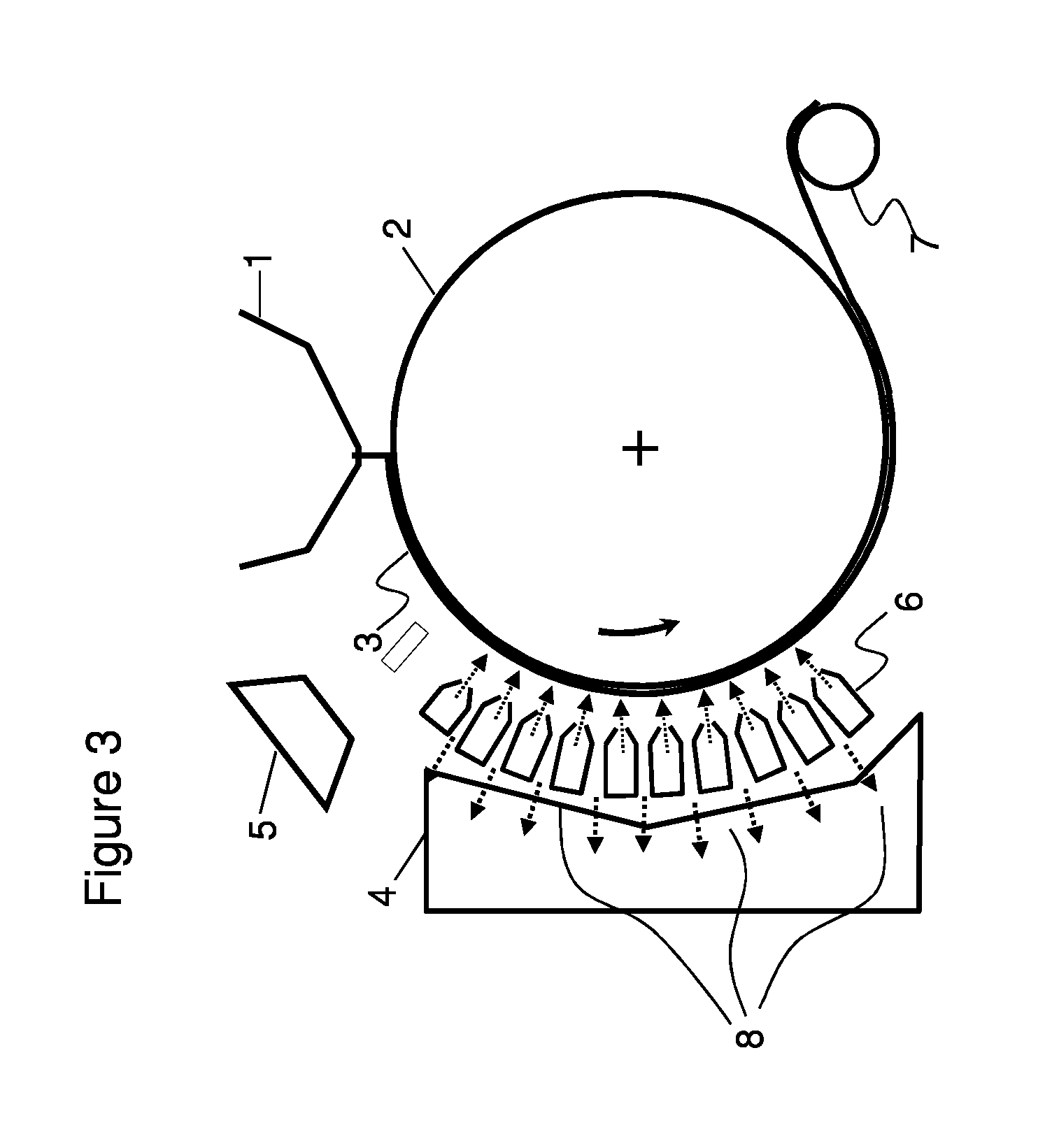
[0017]In the method for producing a thermoplastic resin film of this invention, by keeping the amount of the air sprayed by the cooling device on the side of the anti-cooling drum-side surface larger than the sucked amount, in order to prevent the air with a high oligomer concentration in the proximity of the extrusion die from being sucked into the cooling device, it can be prevented that the oligomer is precipitated and deposited on the spray nozzles and the suction faces of the inter-nozzle exhaust mechanism in the cooling device. (In this description, the apparatus of the present invention may be called the cooling device as the case may be.) As a result, the foreign matter defects caused by the oligomer can be reduced, and the production yield decline and the cleaning loss caused by the foreign matter defects can be significantly reduced. Further, the suction / discharge mechanism is installed at a position recessed from the tip faces of the spray nozzles in the direction farther away from the film, and consequently even if the oligomer is precipitated on the suction faces more or less, the oligomer is unlikely to fall and be deposited on the film surface.
[0018]Further, the spray nozzles are not required to have heating means such as heaters and the cooling efficiency of the spray nozzles can be assured. Crystallization defects are also unlikely to occur.
[0019]On the other hand, an exhaust mechanism is installed on the side of the anti-cooling drum-side surface and in the proximity of the extrusion die, so that the air exhaust may be excessive in the balance between air supply and air exhaust in the chamber as a whole, and so that the air with a high oligomer concentration in the proximity of the aforementioned extrusion die may be discharged while simultaneously the air sprayed from the first spray nozzle of the cooling device and blown up in the extrusion die direction may be discharged. With this configuration, the cleanness in the chamber as a whole can be secured, and at the same time the instability at the landing site of the molten thermoplastic resin right under the extrusion die caused by the blowup of the sprayed air can also be improved.
[0020]Therefore, both the troubles of foreign matters and crystallization defects on the surface of a thick film with a thickness of more than about 150 μm caused by the oligomer, which were difficult to solve by conventional production techniques can be solved by the film obtained in this invention, and the film can be mainly used in connection with displays, more particularly, is suitable as a light diffusion layer of a diffusion plate, a prism layer of a prism sheet, a reflection preventive layer of a reflection preventive film, and a substrate of an optically functional film used for processing a polarizing plate.

Problems solved by technology

The reason is that in the case where a thick film is cooled by a cooling drum only, the film temperature of the anti-cooling drum-side surface does not easily decline to a desired temperature.
Especially in the case of a film made of a crystalline resin such as a polyester, unless the cooling rate near the glass transition temperature of the thermoplastic resin is high enough, the crystallization of the thermoplastic resin progresses to lower the transparency of the film as a result.
The oligomer precipitated on the surface of the auxiliary cooling device may be guided by the air sprayed from the auxiliary cooling device, to fall and be deposited on the surface of the film, thereby making foreign matter defects.
On the other hand, if the tip faces of the spray nozzles are brought as close to the thermoplastic resin film as possible, the cooling rate rises, but the oligomer is precipitated on the auxiliary cooling device and sprayed to the thermoplastic resin film, to be deposited on the surface of the thermoplastic resin film, thereby causing foreign matter defects and other troubles in the subsequent steps.
However, the method of positively discharging the air near the film by installing a suction / discharge mechanism in such a manner as to keep portions of the mechanism disposed between respective spray nozzles as described above not only has a problem of sucking the oligomer air near the film and volatilizing at the spray nozzle portions but also the following problem.
Therefore, as the cooling device is used for a longer period of time, the amount of the oligomer precipitated on the suction faces of the exhaust mechanism increases, and the precipitated oligomer falls on the surface of the thermoplastic resin film, to thereby cause foreign matter defects.
As a result, the foreign matter defects increase with the lapse of time, to incur a loss due to the defects caused by use of the auxiliary cooling device, thereby lowering the productivity.
Further, in the case where heaters are installed inside the suction faces of the exhaust mechanism in order to prevent the precipitation of the oligomer on the suction faces, heating the suction faces to such a temperature as to prevent the precipitation of the oligomer is required to lower the cooling efficiency of the spray nozzles near the suction faces, thus causing cooling fluctuation and crystallization defects due to partial crystallization on the surface of the thermoplastic resin film.
This, for example, raises the problem of degrading the transparency of the film required to be transparent.
Further, even if the suction faces are heated to such an extent of not inhibiting the cooling function, the suction faces of the exhaust mechanism are very likely to have the oligomer precipitated and deposited thereon after use for a long period of time, and it is difficult to achieve both the requirements of sustaining the cooling efficiency and preventing the oligomer contamination.
As described above, the conventional methods did not allow an excellently transparent optical film to be produced while achieving both the requirements of sustaining the cooling rate and reducing the foreign matter defects caused by the dropping of the oligomer precipitated in the auxiliary cooling device.

Method used


Image

  • Method and apparatus for producing a thermoplastic resin film
  • Method and apparatus for producing a thermoplastic resin film
  • Method and apparatus for producing a thermoplastic resin film

Examples


example 1

[0055]As the raw material of the polyester, pellets of polyethylene terephthalate resin (F20S produced by Toray Industries, Inc.) were dried under reduced pressure, supplied into an extruder, and melt-extruded at 280° C. It was brought into contact with a cooling drum (diameter 1,600 mm) kept at a surface temperature of 20° C. by an electrostatic application method, and simultaneously cooled and solidified using a cooling device, to obtain a thermoplastic resin film with a thickness of 2,100 μm.

[0056]The cooling device had a first spray nozzle disposed in the portion nearest to the extrusion die from which the thermoplastic resin was extruded, and the inter-nozzle exhaust mechanism was perfectly separated from the spray nozzles and installed apart from the rear faces of the spray nozzles by 50 mm. Therefore, the suction face of the inter-nozzle exhaust mechanism was perfectly apart from the tip faces of the spray nozzles, and there were through openings between the respective spray ...

example 2

[0062]Used was a cooling device having the suction faces of an inter-nozzle exhaust mechanism placed between the respective spray nozzles, in which the distance between the tip faces of the spray nozzles and the suction faces of the inter-nozzle exhaust mechanism was set at 100 mm. Therefore, the inter-nozzle exhaust mechanism was not separated from the spray nozzles, and there were no through openings between the respective spray nozzles. Except this configuration, polyester films rolls with a film thickness of 188 μm, a width of 1,000 mm and a length of 2,000 m were obtained as described in Example 1.

example 3

[0063]In the cooling step conditions, the total amount of sprayed air was 120 m3 / min and the total amount of sucked air was 70 m3 / min; hence total amount of sucked air / total amount of sprayed air=0.58. Further, the inter-nozzle exhaust mechanism was separated from the spray nozzles and installed behind the rear faces of the spray nozzles, and through openings were formed between the respective spray nozzles. Thus, polyester film rolls with a film thickness of 188 μm, a width of 1,000 mm and a length of 2,000 were obtained.


PUM

PropertyMeasurementUnit
thicknessesaaaaaaaaaa
thicknessaaaaaaaaaa
widthaaaaaaaaaa

Abstract

A thermoplastic resin film manufacturing method and manufacturing device are disclosed wherein an air volume sprayed by the auxiliary cooling device onto the surface of the film on the opposite side thereof to the cooling drum side thereof is set to be larger than the suction amount by an exhaust mechanism between nozzles, to avoid the suction of the air containing the high concentration of oligomer around the extrusion die into the auxiliary cooling device, thereby preventing precipitation and deposition of the oligomer onto spraying nozzles within the auxiliary cooling device and the suction surface of the exhaust mechanism between nozzles.

Description

TECHNICAL FIELD[0001]The present invention relates to a method and apparatus for producing particularly an optical film with few foreign matter defects on the surface thereof and very excellent optical property uniformity.BACKGROUND ART[0002]In recent years, while various display members represented by liquid crystal displays (LCD) and plasma display panels (PDP) are being reduced in weight and cost, the market for optical films as important members of displays are being expanded. Optical films use various transparent films made of thermoplastic resins such as polyesters like polyethylene terephthalate (PET), acrylic polymers and polycarbonates (PC) as base materials, and in order to impart functionality to the base materials, for example, protective films (hard coating layers) for preventing defects, anti-reflection layers (AR layers), light-condensing / diffusing layers, polarizing sheets and the like are laminated on the base materials as various surface treatments, for obtaining t...

Claims


Application Information

Patent Timeline
Patent Type & Authority Applications(United States)
IPC IPC(8): B29C47/88B29C48/08B29C48/76B29C48/92
CPCB29C47/0021B29C47/8845B29C47/8875B29C2947/00B29L2007/00B29C47/768B29C47/92B29L2011/0075B29C48/917B29C48/08B29C48/768B29C48/92B29C48/914B29C2948/00
Inventor LEE, DOSEOKINOUE, HIROYUKIASO, HIROYUKI
Owner TORAY IND INC
Learn More