Apparatus and method for sensing the position of a susceptor in semiconductor device manufacturing equipment

a susceptor and position sensing technology, which is applied in the direction of measuring devices, instruments, optical means, etc., can solve the problems of shaft twisted, gear abraded, cathode slanting and/or unbalanced cathode level, etc., and achieve the effect of lowering reliability and production yield

Inactive Publication Date: 2008-01-31
SAMSUNG ELECTRONICS CO LTD
View PDF7 Cites 1 Cited by
  • Summary
  • Abstract
  • Description
  • Claims
  • Application Information

AI Technical Summary

Benefits of technology

[0010]The slanting or unbalancing of the cathode in the process chamber may lead to various problems. For example, in case the cathode is slanted, an inner wall of the process chamber is scratched. This scratching may cause the dropping of polymer that was generated in the etching process and was fixed to the inner wall, thus polluting a wafer. Furthermore, if the cathode is slanted, a horizontal level of wafer loaded on the cathode also becomes unbalanced. This unbalancing may lead to etching rates for respective positions of wafers to differ substantially, lowering the reliability and the production yield of semiconductor device manufacturing equipment.

Problems solved by technology

However, there may be a case where the cathode is slanted and / or a level of the cathode is unbalanced due to problems with the semiconductor manufacturing equipment.
For example, a fixation screw of ball screw may loosen which may lead to a shaft being twisted, or a gear being abraded.
In addition, or alternatively, a chain may loosen up and may unbalance the cathode.
The slanting or unbalancing of the cathode in the process chamber may lead to various problems.
This scratching may cause the dropping of polymer that was generated in the etching process and was fixed to the inner wall, thus polluting a wafer.
Furthermore, if the cathode is slanted, a horizontal level of wafer loaded on the cathode also becomes unbalanced.
This unbalancing may lead to etching rates for respective positions of wafers to differ substantially, lowering the reliability and the production yield of semiconductor device manufacturing equipment.
While the conventional method of ensuring the proper level and balance of the cathode is useful, it suffers from various limitations.
Furthermore, because the balance of the cathode can be only checked during the PM, there is a problem in that the level of the cathode cannot be monitored in real time.
Therefore, immediate damage to the equipment and wafers caused due to the unbalancing of the cathode cannot be prevented.

Method used


Image

  • Apparatus and method for sensing the position of a susceptor in semiconductor device manufacturing equipment
  • Apparatus and method for sensing the position of a susceptor in semiconductor device manufacturing equipment
  • Apparatus and method for sensing the position of a susceptor in semiconductor device manufacturing equipment

Examples


Embodiment Construction

[0023]Embodiments of the present invention now will be described more fully hereinafter with reference to the accompanied drawings, in which embodiments of the invention are shown. This invention may, however, be embodied in many different forms and should not be construed as limited to the embodiments set forth herein. Rather these embodiments are provided so that this disclosure will be thorough and complete, and will fully convey the scope of the invention to those skilled in the art.

[0024]Unless otherwise defined, all terms (including technical and scientific terms) used herein have the same meaning as commonly understood by one of ordinary skill in the art to which this invention belongs. It will be further understood that terms used herein should be interpreted as having a meaning that is consistent with their meaning in the context of this specification and the relevant art and will not be interpreted in an idealized or overly formal sense unless expressly so defined herein. ...


PUM


Abstract

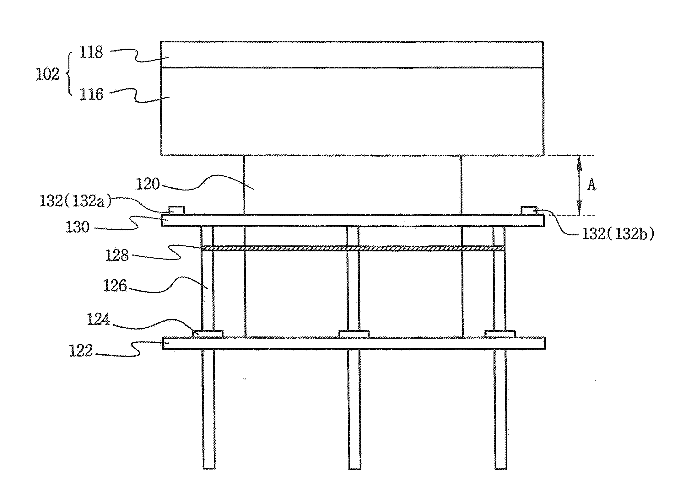
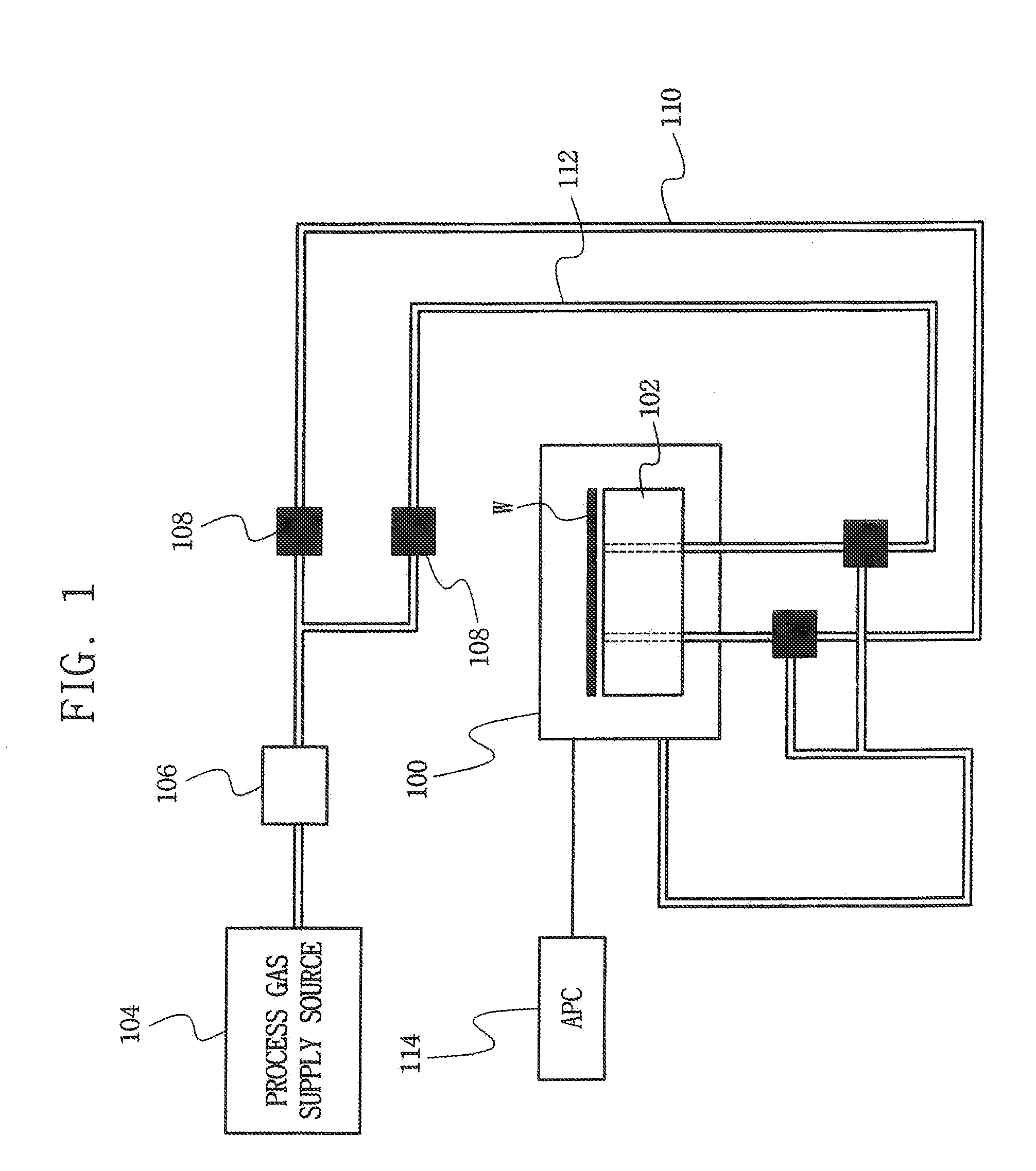
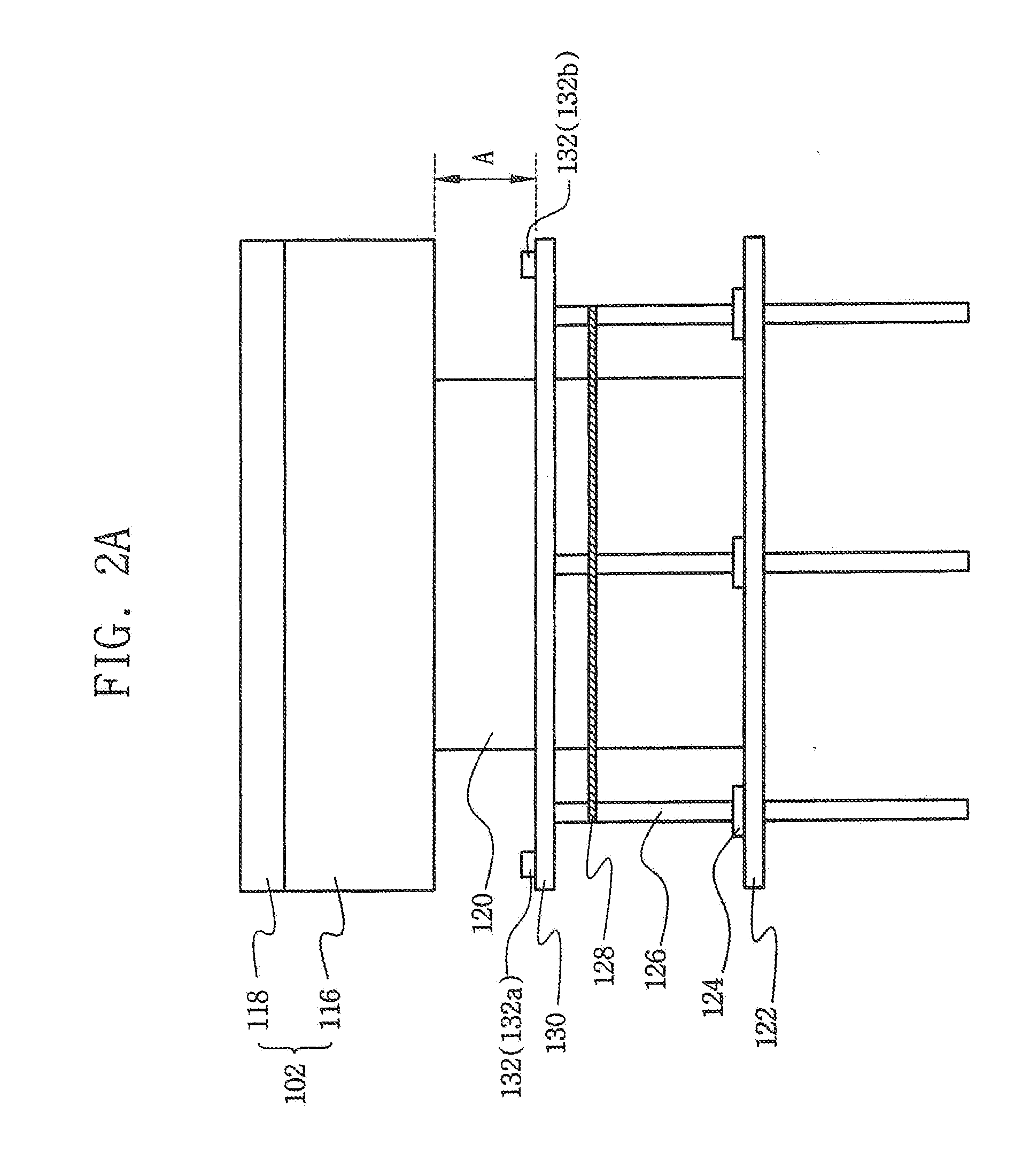
An apparatus for sensing the position of a susceptor in a semiconductor device manufacturing equipment comprises a susceptor which receives a wafer and high frequency power, a sensor unit which irradiates light to a lower face of the susceptor when the susceptor is in a lifted up state and which receives light reflected from the lower face of the susceptor, a light path measuring unit which measures a length of the light reflected to the sensor unit, an operating unit which compares the length of the light measured by the light path measuring unit with reference data indicating a rising height of the susceptor, and which decides whether the length of the measured light is within a range of the reference data, and a controller which interlocks a process equipment when the length of the measured light deviates from the range of the reference data, and which controls a horizontal level state of the susceptor.

Description

BACKGROUND AND SUMMARY[0001]1. Field of the Invention[0002]The present invention relates to semiconductor device manufacturing equipment and, more particularly, to a susceptor positional sensing apparatus for use in semiconductor device manufacturing equipment, and a method of sensing a position of a susceptor.[0003]A claim of priority under 35 U.S.C. §119 is made to Korean Patent Application 10-2006-0071893, filed on Jul. 31, 2006, the contents of which are hereby incorporated by reference in their entirety for all purposes as if fully set forth herein.[0004]2. Description of the Related Art[0005]The manufacturing cycle of a semiconductor device includes a number of unit processes. These unit processes include, for example, an impurity ion implantation process, a thin film deposition process, an etching process, a CMP(Chemical Mechanical Polishing) process, and a cleaning process. Typically, the impurity ion implantation process involves implanting impurity ions of group 3B, e.g., ...

Claims


Application Information

Patent Timeline
Patent Type & Authority Applications(United States)
IPC IPC(8): G01B11/14
CPCG01B11/026
Inventor SHIN, JEONG-CHEOL
Owner SAMSUNG ELECTRONICS CO LTD
Why Eureka
Try Eureka