Print head pressure control architectures

a control architecture and print head technology, applied in the direction of liquid surface applicators, coatings, printing, etc., can solve the problems of preventing a “de-prime” condition, using negative pressure or capillary materials, and slowing the fluid refilling of the inkjet print head nozzle, so as to improve the robustness of the inkjet tank/cartridge

Inactive Publication Date: 2005-07-21
FUJIFILM BUSINESS INNOVATION CORP
View PDF7 Cites 11 Cited by
  • Summary
  • Abstract
  • Description
  • Claims
  • Application Information

AI Technical Summary

Benefits of technology

[0010] In various exemplary embodiments of the systems and methods according to this invention, a ratio of from about 0.3 to 1 to about 3.0 to 1, preferably from about 0.5 to 1 to about 2 to 1, and more preferably from about 1 to 1 is achieved between the volume of an inkjet tank/cartridge negative pressure medium chamber and the v...

Problems solved by technology

However, the use of a negative pressure or capillary material, such as, for example, a foam, has a number of drawbacks.
Additionally, under relatively high ink flow conditions, the foam or other negative pressure material may create an impedance that raises the negative pressure to relatively unacceptable values, which in turn slows the fluid refill of the inkjet print head nozzles, and may, under certain circumstances, create a “starved jet” condition, i.e., one in which ink is not supplied to the print head in sufficient volume for proper inkjet print head operation.
Also, the foam or other negative pressure material in an ink tank is typically only partially saturated and contains a mixture of air and ink which may make it difficult under certain circumstances to prevent a “de-...

Method used


Image

  • Print head pressure control architectures
  • Print head pressure control architectures
  • Print head pressure control architectures

Examples


Embodiment Construction

[0037] The following detailed description of various exemplary embodiments of the fluid containers usable with fluid ejection systems or other technologies that store and consume fluids, according to this invention may refer to one specific type of fluid ejection system, e.g., an inkjet printer that uses the refillable fluid containers according to this invention, for sake of clarity and familiarity. As applied herein, fluids refer to non-vapor (i.e., relatively incompressible) flowable media, such as liquids, slurries and gels. However, it should be appreciated that the principles of this invention, as outlined and / or discussed below, can be equally applied to any known or later-developed fluid ejection systems, beyond the ink jet printer specifically discussed herein. In addition, it should be appreciated that the principles of this invention can also be applied to other fluid containing systems in which ventilation is required. Such fluid-ejection applications include, but are no...


PUM


Abstract

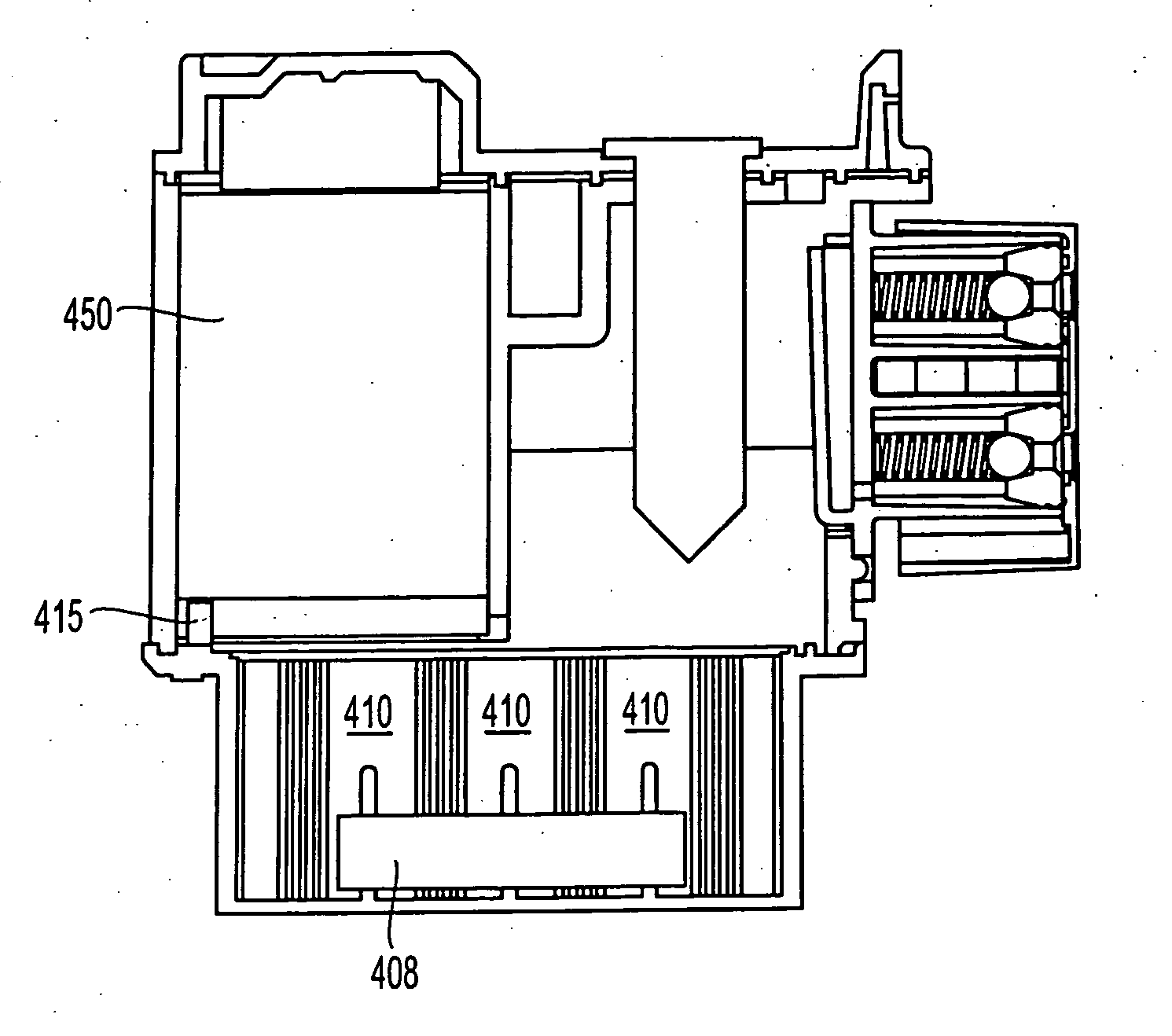
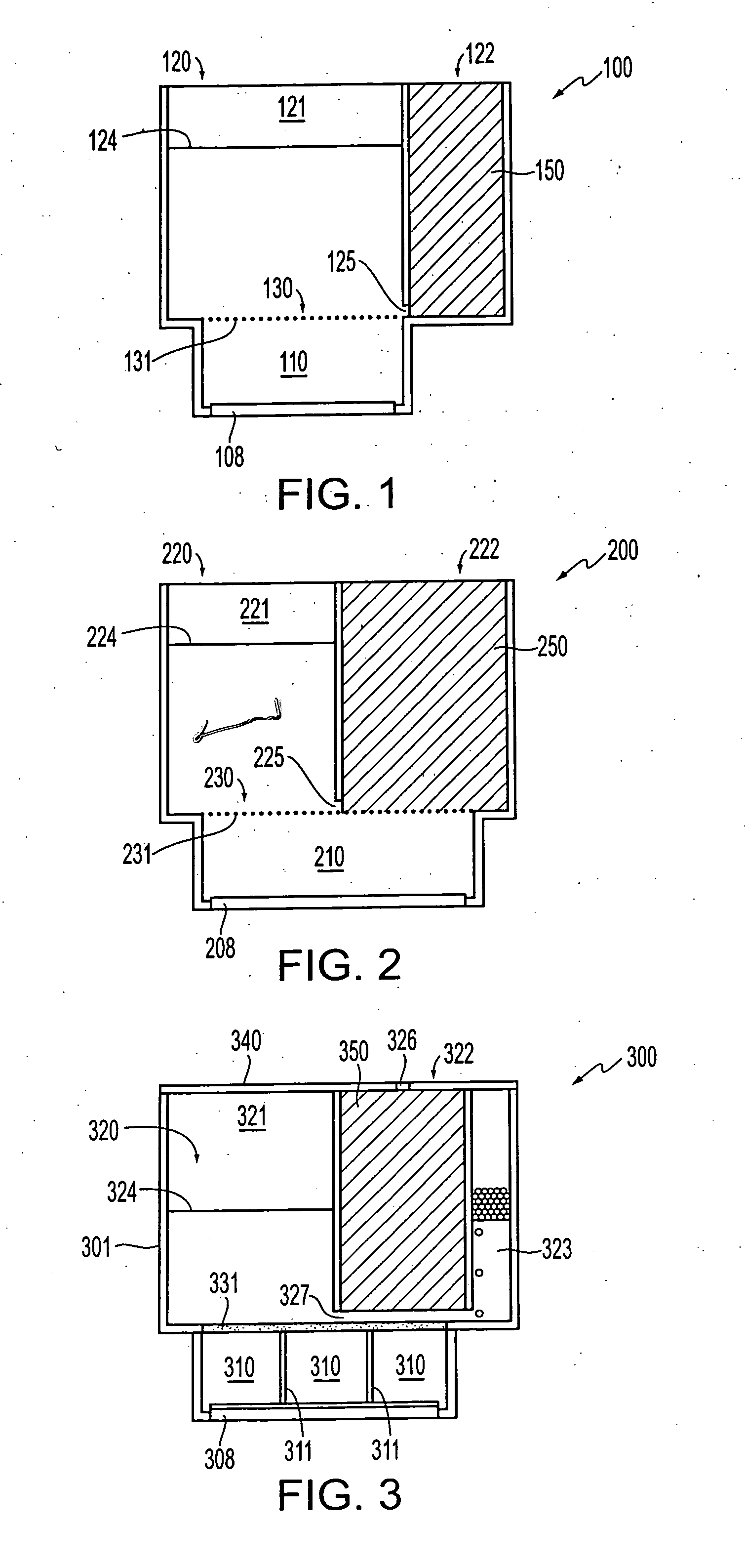
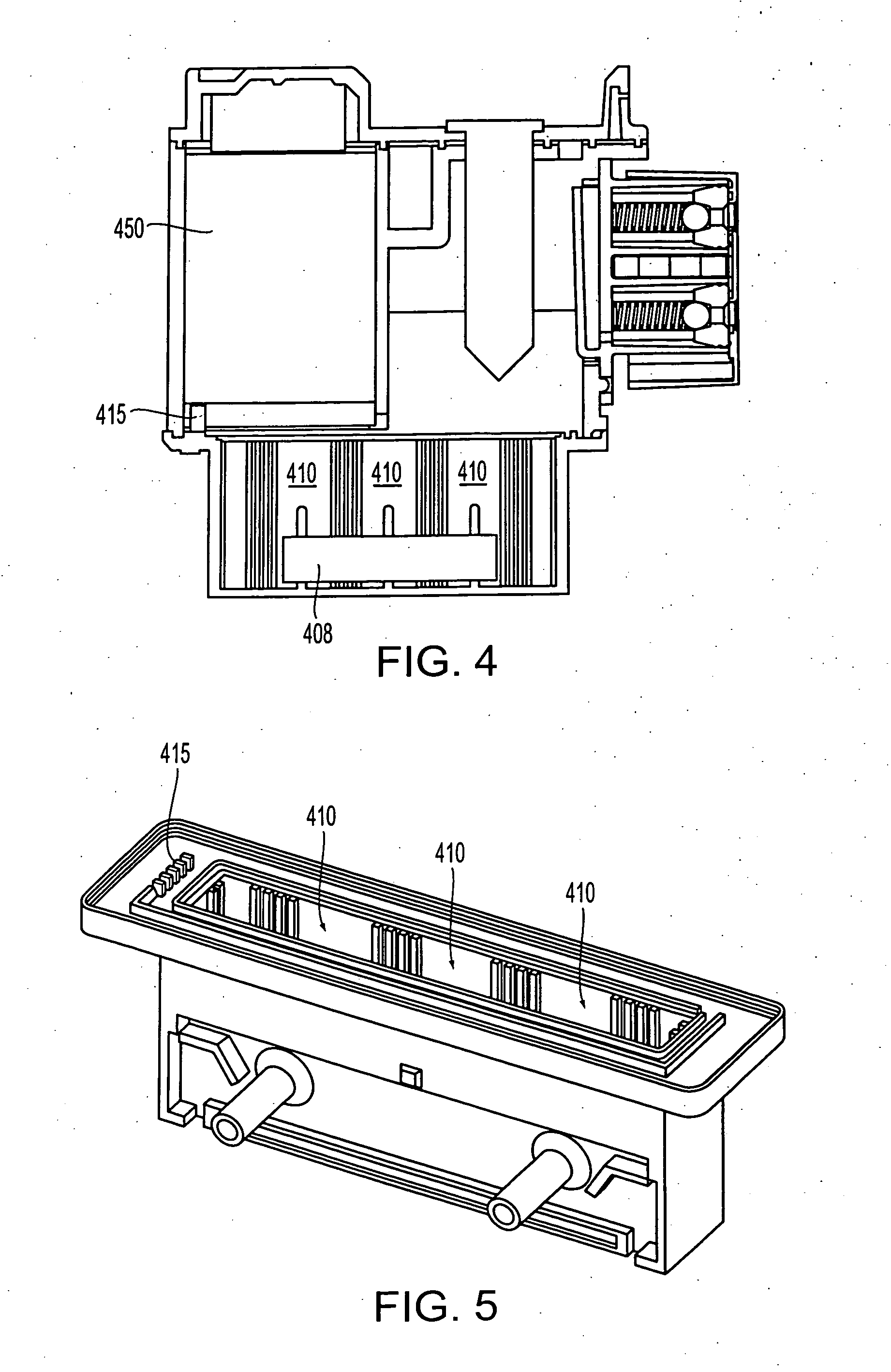
A fluid container, such as, for example, an inkjet print head cartridge, architecture uses a relatively large filter that is located below a negative pressure material chamber and a free ink chamber in a side-by-side relationship. The negative pressure material volume relative to a free ink chamber value can me made to be approximately one to one. Both chambers overlie an ink manifold/delivery port and are separated from the delivery port by a filter. Flow impedance of the cartridge is reduced, as a result, in any orientation of the cartridge. The filter may be separated from, or in contact with a negative pressure material. A cartridge lid is provided with a negative pressure material chamber which is suspended into the cartridge. A negative pressure material having a fiber felt construction is provided.

Description

BACKGROUND OF THE INVENTION [0001] 1. Field of Invention [0002] This invention is directed to controlling pressure at the print head of an inkjet marker. [0003] 2. Description of Related Art [0004] Typically, fluid pressure of an inkjet print head is maintained within a tightly controlled range. A negative pressure is usually maintained in an ink tank which is connected to an inkjet print head in order to prevent ink from weeping out of the openings or nozzles of the print head. One conventional method for accomplishing such a negative pressure uses a capillary medium, such as, for example, foam. However, the use of a negative pressure or capillary material, such as, for example, a foam, has a number of drawbacks. [0005] For example, the volumetric efficiency of an ink tank container is reduced by the amount of space which is occupied by the foam or other negative pressure material. Additionally, under relatively high ink flow conditions, the foam or other negative pressure material...

Claims


Application Information

Patent Timeline
IPC IPC(8): B05C5/00B05C11/10B41J2/175
CPCB41J2/17563B41J2/17513
Inventor MERZ, ERIC A.HILTON, BRIAN S.ODA, KAZUYUKITSUCHIYA, TAKATOSHI
Owner FUJIFILM BUSINESS INNOVATION CORP
Why Eureka
Try Eureka