Projection display systems for light valves

a technology of projection display and light valve, which is applied in the direction of picture reproducers using projection devices, instruments, non-linear optics, etc., can solve the problems of large system complexity, complicated prefiltering system, and large complexity of projection system for reflective liquid crystal display (lcd), so as to reduce the overall projection display system size and complexity, reduce the size of distribution and recombination system, and reduce the effect of complexity

Inactive Publication Date: 2005-07-21
SHARP KK
View PDF52 Cites 22 Cited by
  • Summary
  • Abstract
  • Description
  • Claims
  • Application Information

AI Technical Summary

Benefits of technology

[0015] The various aspects of the present invention each have one or more of the following advantages. The systems achieve their advantages through the use of color component rotators, or wavelength-specific retardation filters, located within the optical systems to control the polarization orientation of one of the color components in the system relative to the other two. The use of a color component rotator allows the polarization orientation of the three color components to be controlled within the main color distribution and recombination portion of the system rather than in a prefiltering system included within the illumination optics. This allows the use of conventional polarization converters rather than complicated prefiltering systems.
[0016] In addition, the use of color component rotators enables smaller distribution and recombination systems than conventional reflective projection display systems and, in one case, smaller even than typical transmissive projection display systems. Thus, the projection display systems and methods of the present invention reduce the overall projection display system size and complexity. The systems provide these advantages while achieving good contrast and without sacrificing brightness.

Problems solved by technology

Projection systems for reflective liquid crystal displays (LCDs) are generally characterized by their complexity and large size relative to the systems implemented for transmissive LCDs. FIG. 1A discloses a prior art configuration for a transmissive LCD projector, while FIG. 1B shows a prior art reflective LCD projector for comparison.
These components add complexity to the system and require the use of a larger distribution and recombination optical system to divide the light into the three color channels (i.e. the optical paths traveled by the three color components such as red, green, and blue).
In order to produce that combination of color components and polarizations, a complicated prefiltering system is needed.
This arrangement appears simple, but the control of color in a Philips prism for p-polarization on the input and s-polarization on the output is extremely difficult, and no successful implementation of this type of system exists.
This requires a second optical arrangement to split up the color distributions and leads to a larger, more complicated system overall.
The color splitting and recombination is accomplished by tilted dichroics that perform essentially the same as the dichroics in a Philips prism, with the same polarization related problems.

Method used


Image

  • Projection display systems for light valves
  • Projection display systems for light valves
  • Projection display systems for light valves

Examples


Embodiment Construction

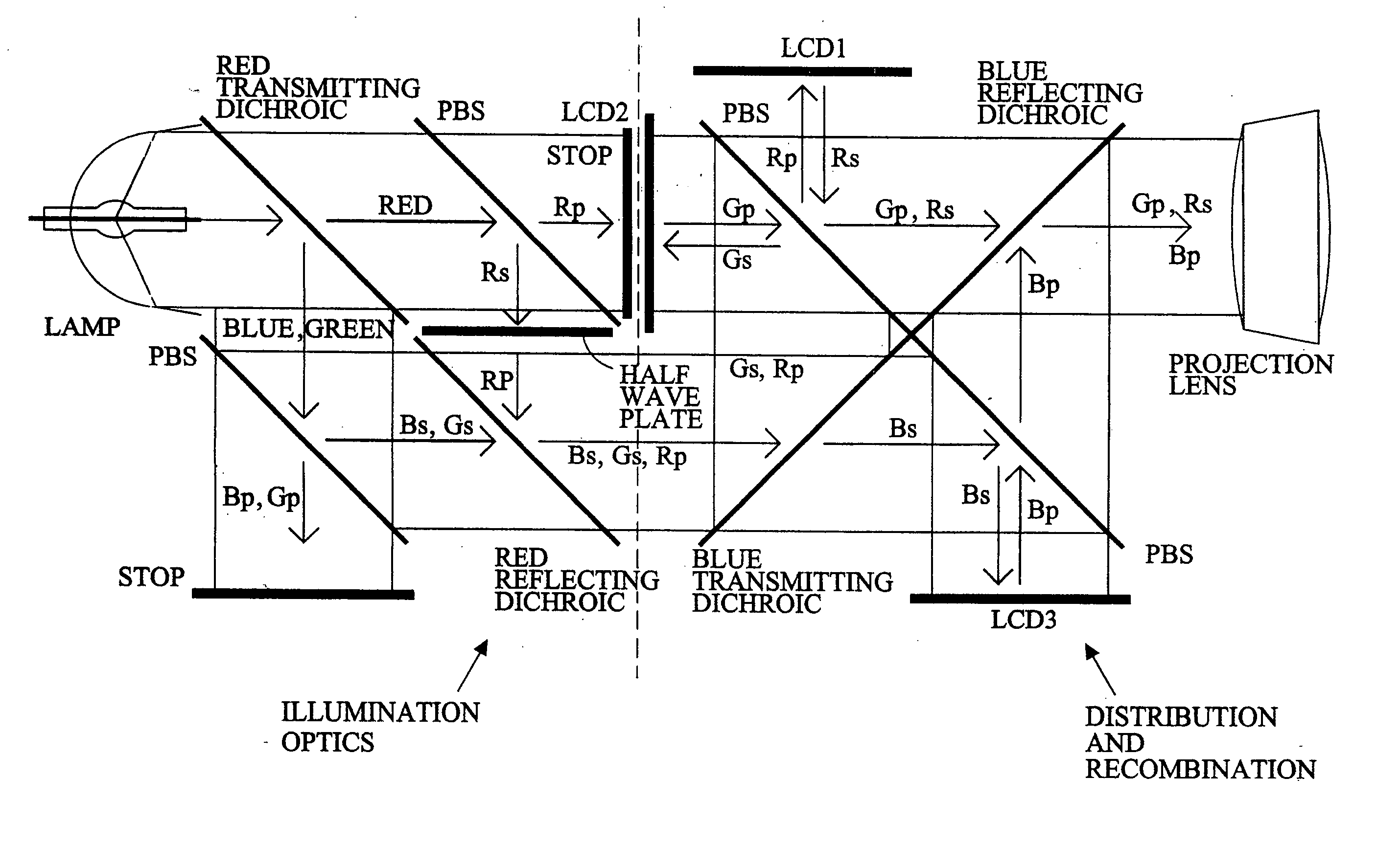
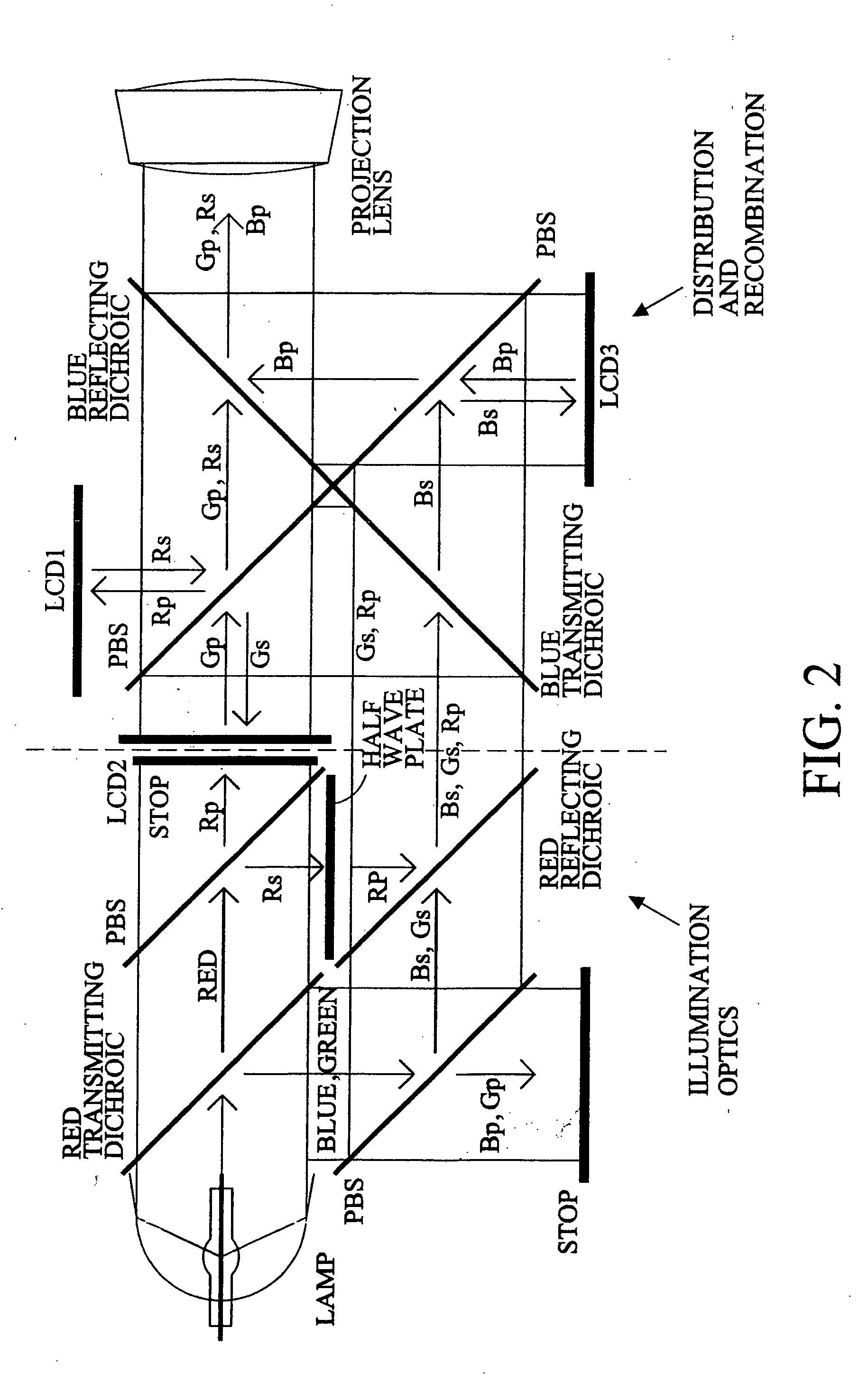
[0026] Referring now to the figures, wherein like numerals refer to like elements, FIG. 3 shows an exemplary projection display 10 having an illumination portion 11 and distribution and recombination portion 22. Distribution and recombination portion 22 includes three reflective liquid crystal display (LCD) panels 14, 16, and 18, also referred to as liquid crystal light valves.

[0027] Illumination portion 11 includes a light source 12 for producing white light, which may be separated into different color components of different bandwidths, such as a red color component, blue color component, and green color component. The white light from light source 12 passes through a polarization converter shown generally at 20. Polarization converter 20 may take the form of any conventional polarization converter, so that the randomly polarized light from light source 12 is converted into a single polarization state. In the embodiment shown in FIG. 3, the polarization converter 20 converts the ...


PUM


Abstract

Projection display systems for light valves such as liquid crystal display panels, and in particular to the use of color component rotators, such as retardation filters, to provide for improved projection display architectures.

Description

CROSS-REFERENCE TO RELATED APPLICATIONS [0001] This application is a divisional application of U.S. patent application Ser. No. 09 / 539,918, filed Mar. 31, 2000, to which it claims priority.BACKGROUND OF THE INVENTION [0002] The present invention relates to projection display systems for light valves such as liquid crystal display panels, and in particular to the use of color component rotators, such as retardation filters, to provide for improved projection display architectures. [0003] Projection systems for reflective liquid crystal displays (LCDs) are generally characterized by their complexity and large size relative to the systems implemented for transmissive LCDs. FIG. 1A discloses a prior art configuration for a transmissive LCD projector, while FIG. 1B shows a prior art reflective LCD projector for comparison. Dichroic filters DF1 and DF2 separate the red, green, and blue color components. The reflective LCDs require a polarizing beamsplitter (PBS) to be placed in front of e...

Claims


Application Information

Patent Timeline
Patent Type & Authority Applications(United States)
IPC IPC(8): G03B21/14G03B21/20H04N9/31
CPCG03B21/14H04N9/3105G03B33/12H04N9/3197G03B21/2073H04N9/315G02B27/1026G02B27/283G03B33/08
Inventor FLORENCE, JAMES M.SAMPSELL, JEFFREY B.HUANG, AUSTIN L.
Owner SHARP KK
Why Eureka
Try Eureka