
Industrial directly diode-pumped ultrafast amplifier system

an ultrafast amplifier and diode pump technology, applied in laser details, active medium materials, laser arrangement, etc., can solve the problems of scaling to higher powers and not fully satisfying the need for an industrial ultrafast amplifier

Inactive Publication Date: 2005-07-21
SPECTRA PHYSICS
View PDF8 Cites 79 Cited by
  • Summary
  • Abstract
  • Description
  • Claims
  • Application Information

AI Technical Summary

Benefits of technology

[0009] An object of the present invention is to provide an improved ultrafast amplifier system, and its methods of use.
[0010] Another object of the present invention is to provide an improved ultrafast amplifier system, and its methods of use, with direct diode pumping of the gain media.
[0011] A further object of the present invention is to provide an improved ultrafast amplifier system, and its methods of use, with computer resources that provide control of various operating parameters of the amplifier system.
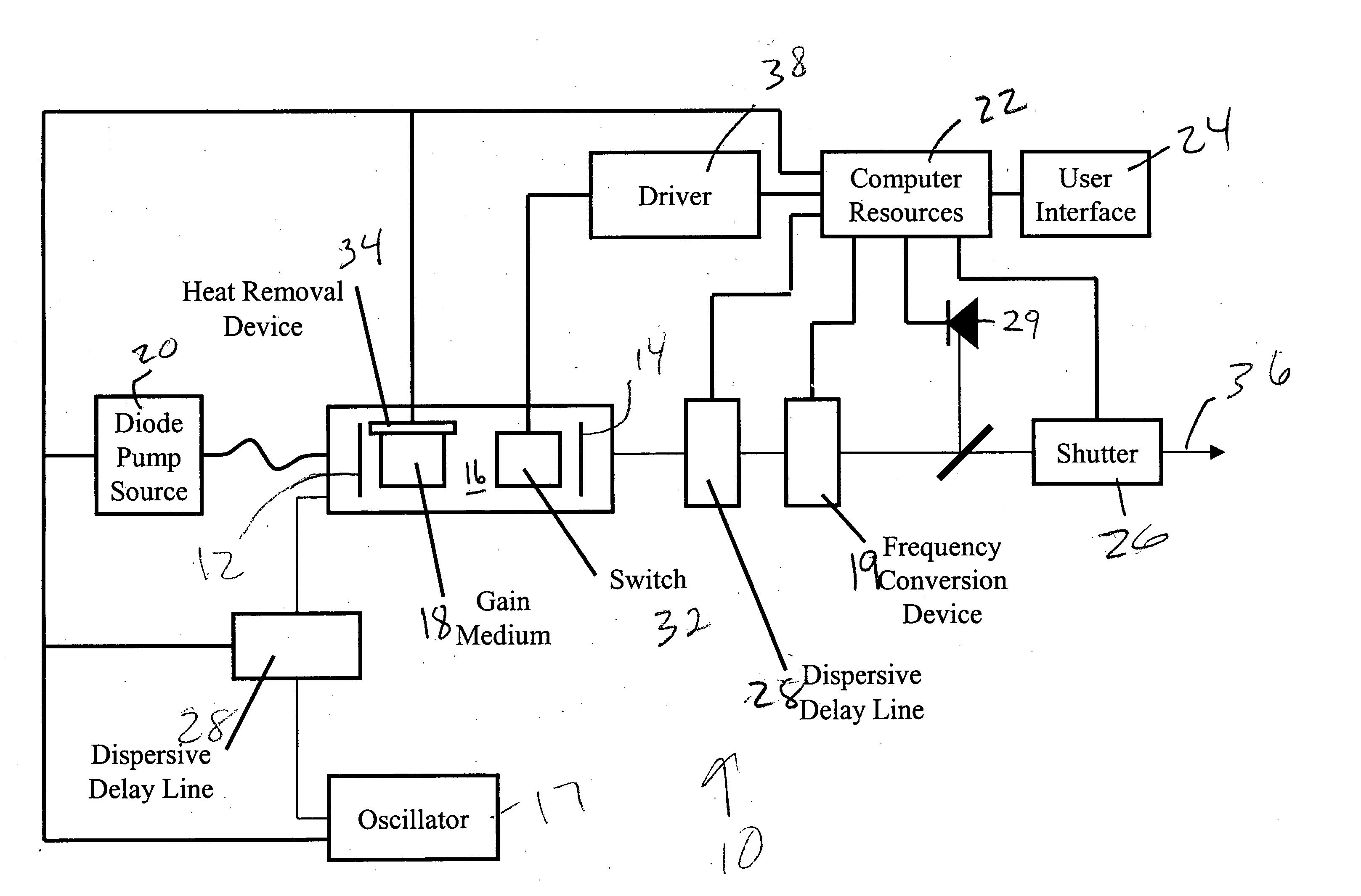
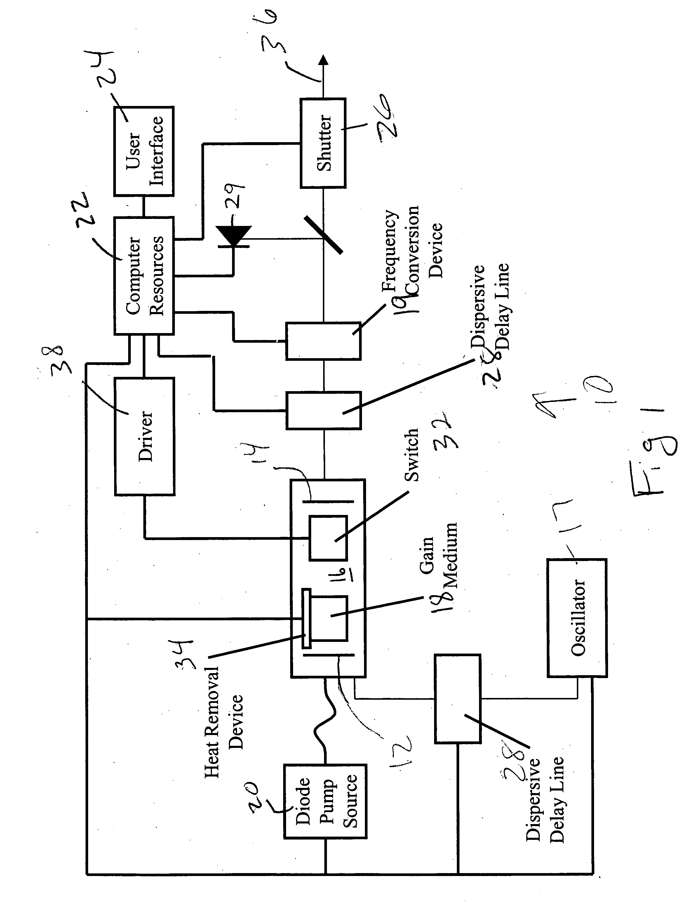
[0012] These and other objects of the present invention are achieved in an amplifier system with first and second reflectors that define an amplifier cavity. A gain media is positioned in the amplifier cavity. A diode pump source directly pumps the gain media and the amplifier system produces sub-picosecond pulses with an output power of 2 watts or more. Computer resources are coupled to the amplifier system and are configured to provide control of operating parameters of the amplifier system.
[0013] In ano...

Problems solved by technology

While these systems have found wide use in scientific applications, they do not fully satisfy the need for an industrial ultrafast amplifier.
This is because the thermal conductivity is small for the bulk Yb doped gain media and thus scaling to higher powers is problematic.

Method used


Image

  • Industrial directly diode-pumped ultrafast amplifier system
  • Industrial directly diode-pumped ultrafast amplifier system

Examples


example 1

[0034] The ultrafast pulses of the present invention are used at the fundamental wavelength of 1048 nm to machine various materials. In one embodiment, 50 micron diameter round holes are drilled through 1 mm thick hardened steel. Using 2.5 W of average power at 5 kHz repetition rate, the holes are completed in 20 seconds.

example 2

[0035] In this example, ultrafast pulses of the present invention are used for scribing of borosilicate glass with 30-micron wide, chip-free grooves. This is done at 2 kHz repetition rate and a scan speed of at least 10 mm / sec.

example 3

[0036] In this example, ultrafast pulses of the present invention are used for scribing of the nanocomposite Morthane with 26 micron wide and 20 micron deep clean grooves generated. The repetition rate is 5 kHz and 10 passes are required and a scan speed of at least 40 mm / sec can be used to generate these grooves.


PUM


Abstract

A directly diode-pumped amplifier system is disclosed which produces sub-picosecond pulses with an output power of 2 watts or more. Computer resources are coupled to the amplifier system and are configured to provide control of operating parameters of the amplifier system. An optional second harmonic generator is supplied to increase the contrast ratio and reduce the minimum focal spot size. This amplifier system can be utilized for material processing applications.

Description

CROSS REFERENCE TO RELATED APPLICATION [0001] This application claims the benefit of provisional Application No. 60 / 535,080, filed Jan. 7, 2004, and U.S. Ser. No. 10 / 762,216 filed Jan. 20, 2004, both of which are fully incorporated by reference.BACKGROUND [0002] 1. Field of the Invention [0003] This invention relates generally to ultrafast amplifier systems, and their methods of use, and more particularly to ultrafast amplifier systems with direct diode pumping of the gain media, and their methods of use. [0004] 2. Description of the Related Art [0005] Ultrafast amplifier systems have been used in both scientific and industrial applications for the last decade. The most common system uses Ti:sapphire as the gain media and produces about 1 mJ of energy at 1 kHz repetition rate with a pulse duration of 150 fs. While these systems have found wide use in scientific applications, they do not fully satisfy the need for an industrial ultrafast amplifier. The Ti:sapphire system requires gre...

Claims


Application Information

Patent Timeline
IPC IPC(8): H01S3/042H01S3/0941H01S3/098H01S3/16H01S3/23
CPCH01S3/0092H01S3/042H01S3/0941H01S3/2308H01S3/1312H01S3/1618H01S3/1675H01S3/1022
Inventor KAFKA, JAMES D.ZHOU, JIANPINGAUS-DER-AU, JUERGHOLSINGER, KEVINSTOEV, VENTZISLAV
Owner SPECTRA PHYSICS
Learn More