Plasma processing apparatus

Active Publication Date: 2005-07-28
COMMSCOPE TECH LLC +1
View PDF5 Cites 199 Cited by
  • Summary
  • Abstract
  • Description
  • Claims
  • Application Information

AI Technical Summary

Benefits of technology

[0027] In this case, it is preferable that the circular antenna is provided with first slots of a predetermined length disposed along a circle located inwardly by λg/4 from the periphery of the circular antenna and second slots of a specified length disposed on one or more concentric circles located inwardly at intervals of λg/2 from the first slots. Further, it is pref

Problems solved by technology

However, the microwave oscillator 91 using the magnetron 91a has a drawback such as the high cost for the equipment and the maintenance thereof due to a short life of about half a year of the magnetron 91a. Further, since the magnetron 91a has oscillation stability of approximately 1% and output stability of approximately 3%, resulting in a large difference therebetween, it is difficult to transmit a stable microwave.
In case of impedance mismatching, power loss can be increased.
Further, in

Method used


Image

  • Plasma processing apparatus
  • Plasma processing apparatus
  • Plasma processing apparatus

Examples


Example

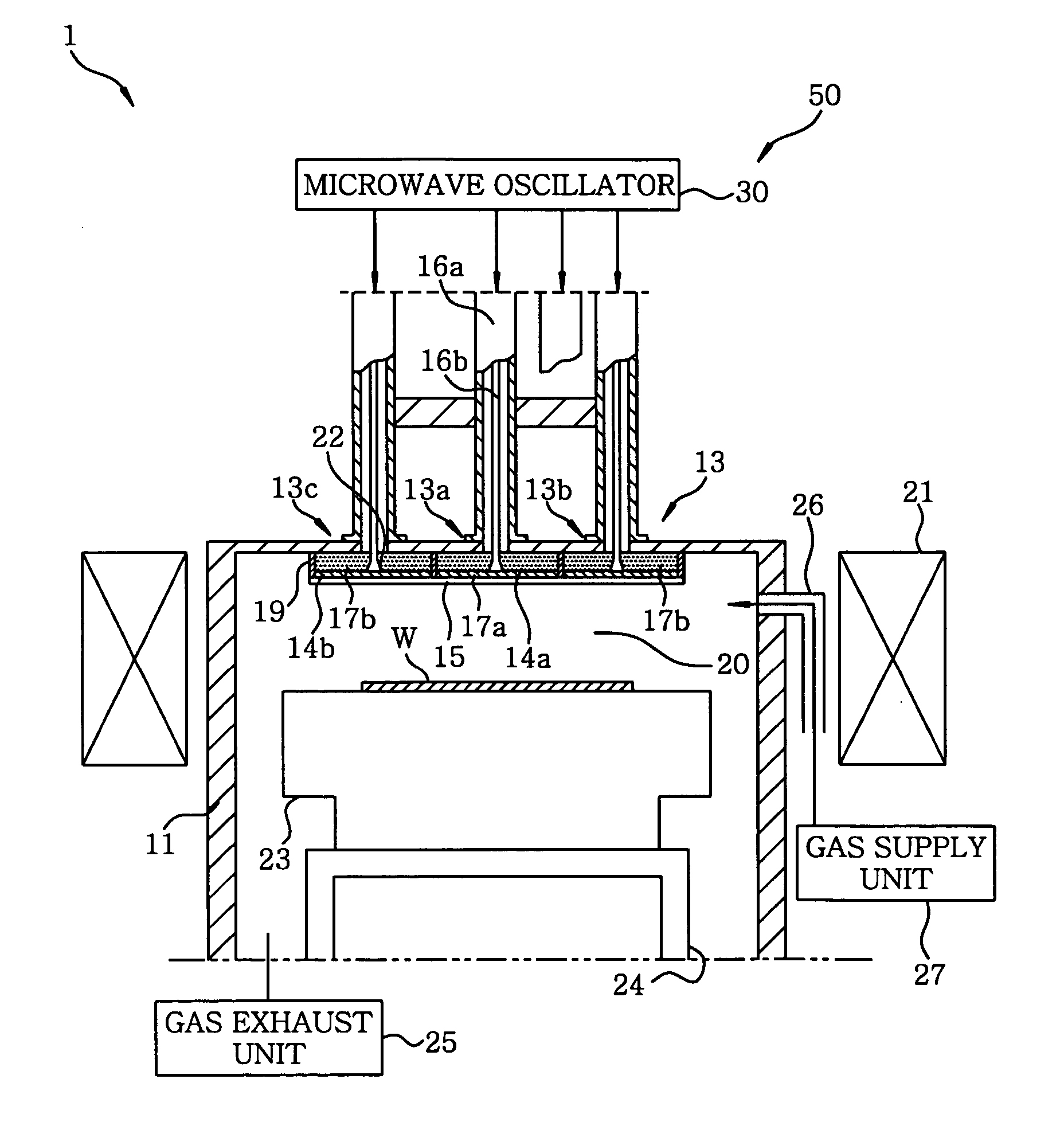
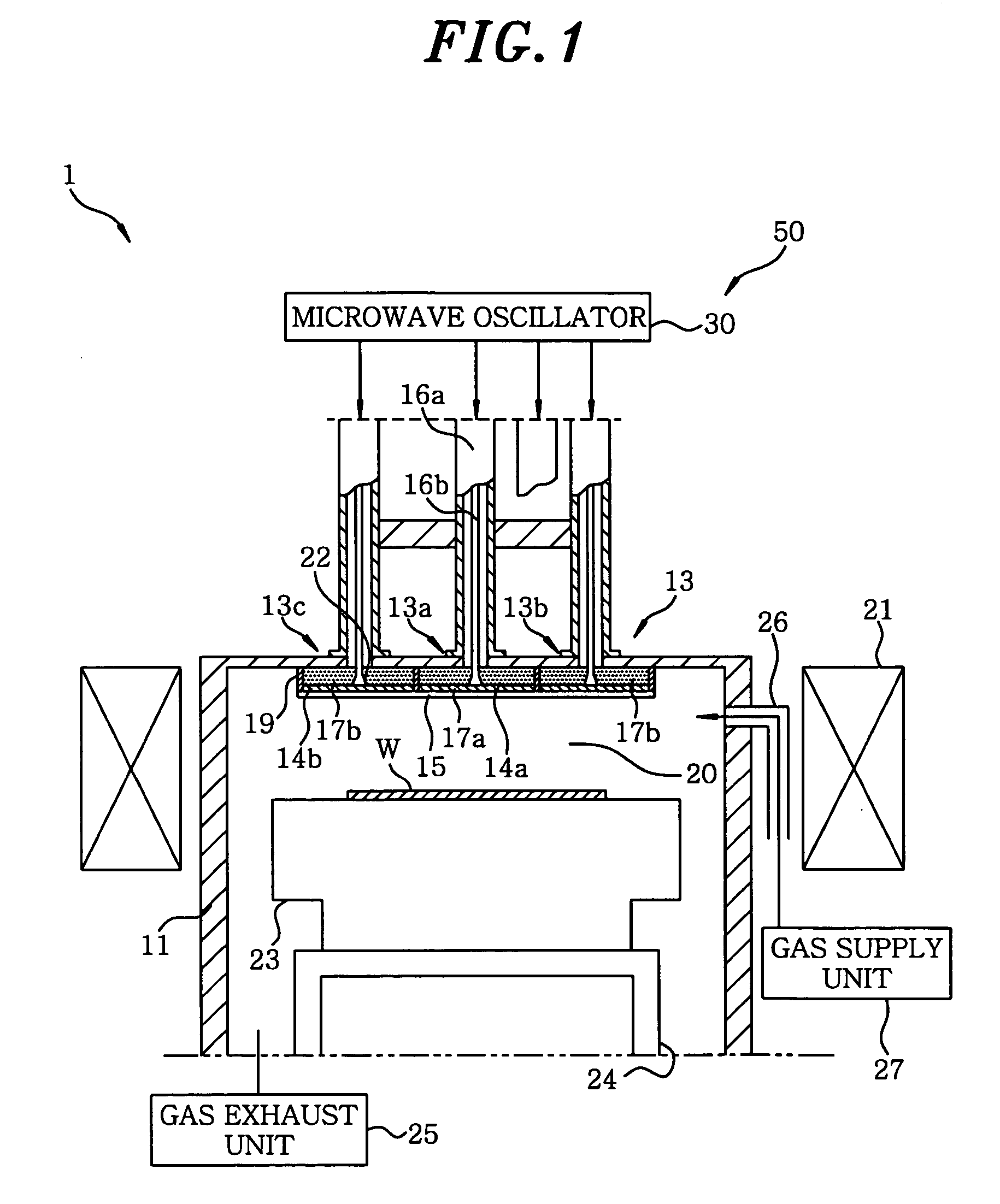
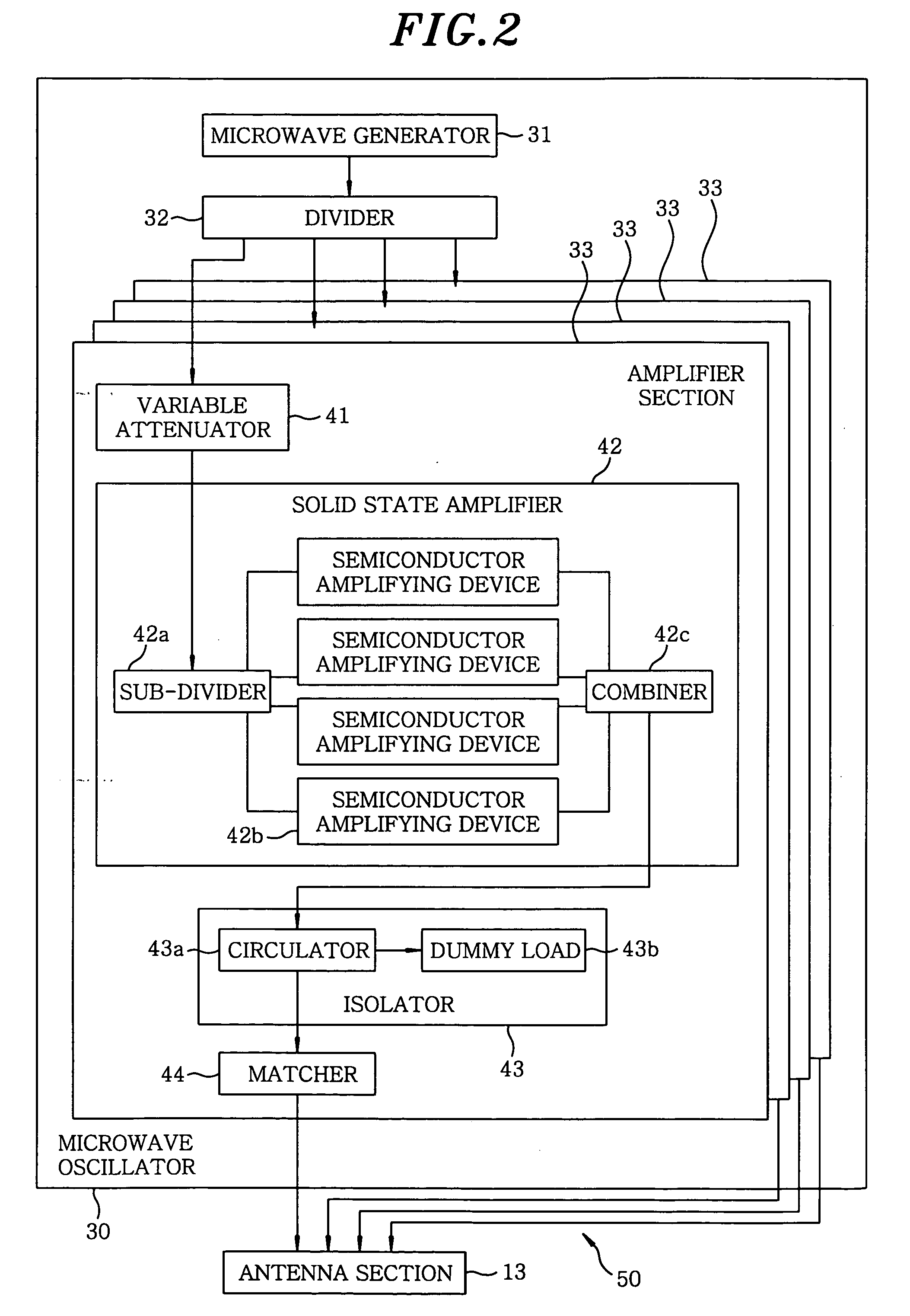
[0037] Hereinafter, preferred embodiments of the present invention will be described with reference to the accompanying drawings. FIG. 1 shows a schematic cross sectional view of a plasma etching apparatus 1 as an example of a plasma processing apparatus. FIG. 2 is an explanatory diagram showing a detailed configuration of a microwave introducing unit 50 installed in the plasma etching apparatus 1. Further, in the plasma etching apparatus 1, a substrate to be processed is a semiconductor wafer W.

[0038] The plasma etching apparatus 1 includes a chamber 11 for containing the wafer W therein; a gas inlet opening 26 provided in the chamber 11; a gas supply unit 27 which supplies a processing gas (e.g., Cl2) for producing a plasma into the chamber 11 through the gas inlet opening 26; a gas exhaust port 24 installed in the chamber 11; a gas exhaust unit 25 for exhausting an inside of the chamber 11 through the gas exhaust port 24; a substrate support stage 23 for supporting the wafer W i...


PUM

PropertyMeasurementUnit
Poweraaaaaaaaaa
Magnetic fieldaaaaaaaaaa

Abstract

A plasma processing apparatus includes a chamber for containing a substrate to be processed, a gas supply unit for supplying a processing gas into the chamber, and a microwave introducing unit for introducing plasma generating microwaves into the chamber. The microwave introducing unit includes a microwave oscillator for outputting a plurality of microwaves having specified outputs, and an antenna section having a plurality of antennas to which the microwaves outputted from the microwave oscillator are respectively transmitted.

Description

[0001] This application is a Continuation Application of PCT International Application No. PCT / JP03 / 12792 filed on Oct. 6, 2003, which designated the United States.FIELD OF THE INVENTION [0002] The present invention relates to a plasma processing apparatus for performing a plasma process such as an etching on a substrate to be processed. BACKGROUND OF THE INVENTION [0003] In a manufacturing process of a semiconductor device or a liquid crystal display device, a plasma processing apparatus such as a plasma etching apparatus and a plasma CVD film forming apparatus has been employed to perform a plasma process, e.g., an etching process or a film forming process, on a substrate to be processed such as a semiconductor wafer and a glass substrate. [0004] There are well-known plasma generating methods used in the plasma processing apparatus, e.g., a method including steps of supplying a processing gas into a chamber with parallel plate electrodes disposed therein; feeding a specific power ...

Claims


Application Information

Patent Timeline
IPC IPC(8): C23C16/00C23F1/00
CPCH05B6/705
Inventor KASAI, SHIGERUOSADA, YUKIOGINO, TAKASHI
Owner COMMSCOPE TECH LLC
Why Eureka
Try Eureka