Method of manufacturing ceramic honeycomb structural body, and ceramic honeycomb structural body

a technology of ceramic honeycomb and structural body, which is applied in the direction of metal-working apparatus, machines/engines, buttons, etc., can solve the problems of inconvenient operation, difficult to correctly dispose of masks, and high labor intensity, so as to facilitate the drilling of holes in sheets, improve labor intensity, and improve the effect of yield

Inactive Publication Date: 2005-07-28
NGK INSULATORS LTD
View PDF17 Cites 10 Cited by
  • Summary
  • Abstract
  • Description
  • Claims
  • Application Information

AI Technical Summary

Benefits of technology

[0015] Moreover, in the method of manufacturing the ceramic honeycomb structure of the present invention, the other cells are divided into a plurality of blocks in such a manner as to include the reference cells, and the holes are preferably drilled for each of the blocks. When the cells are divided into the blocks in this manner, the shapes of the cells or the intervals of the cell pitches in this region deform little, and therefore the step of drilling the holes in the sheets is facilitated.
[0016] Furthermore, in the method of manufacturing the ceramic honeycomb structure of the present invention, a ratio of an opening area of each of the holes to an area of the opening part of each of the other cells in the end face is preferably 30 to 70%. By this constitution, the hole can be effectively prevented from being drilled over cell walls for partitioning the respective cells, or adjacent cells.
[0017] On the other hand, a ceramic honeycomb structure of the present invention is preferably manufactured by one of the above-described methods of manufacturing the ceramic honeycomb structure of the present invention. By the use of the manufacturing method constituted in this manner, manufacturing steps are simplified, further a yield is raised, and the obtained ceramic honeycomb structure can be inexpensive.

Problems solved by technology

However, in the above-described method of manufacturing the ceramic honeycomb structure, as shown in FIG. 8(a), there have been inconveniences that the masks 24, 25 having the holes 23 in the positions corresponding to the opening parts of the cells 22 are prepared and that it is difficult to correctly dispose the masks 24, 25 on the respective end faces of the ceramic honeycomb body 21.
Since the masks 24, 25 are disposed on the respective end faces of the ceramic honeycomb body 21 by the manual operation, there have been inconveniences that operator's skill is required, much time is taken, and it is impossible to cope with automation.
Furthermore, to reuse the masks 24, 25, the masks need to be cleaned after end of the operation, but the enormous number of the holes are made in the masks 24, 25 as described above, and therefore there has also been an inconvenience that the cleaning is troublesome and time-consuming.
However, in the above-described method of manufacturing the ceramic honeycomb structure, there has been a problem that it is remarkably difficult to position the holes to be drilled in the sheets with respect to the opening parts in several tens of thousands of cells of the ceramic honeycomb structure in manufacturing the large-sized ceramic honeycomb structure.
In a case where the holes are not correctly positioned, there has also been a problem that the holes are drilled in the same cell-in the opposite end faces, and an object to alternately seal the cells cannot be achieved.
When the ceramic honeycomb body is even slightly curved / deformed, the above-described problem is further complicated.

Method used


Image

  • Method of manufacturing ceramic honeycomb structural body, and ceramic honeycomb structural body
  • Method of manufacturing ceramic honeycomb structural body, and ceramic honeycomb structural body
  • Method of manufacturing ceramic honeycomb structural body, and ceramic honeycomb structural body

Examples


Embodiment Construction

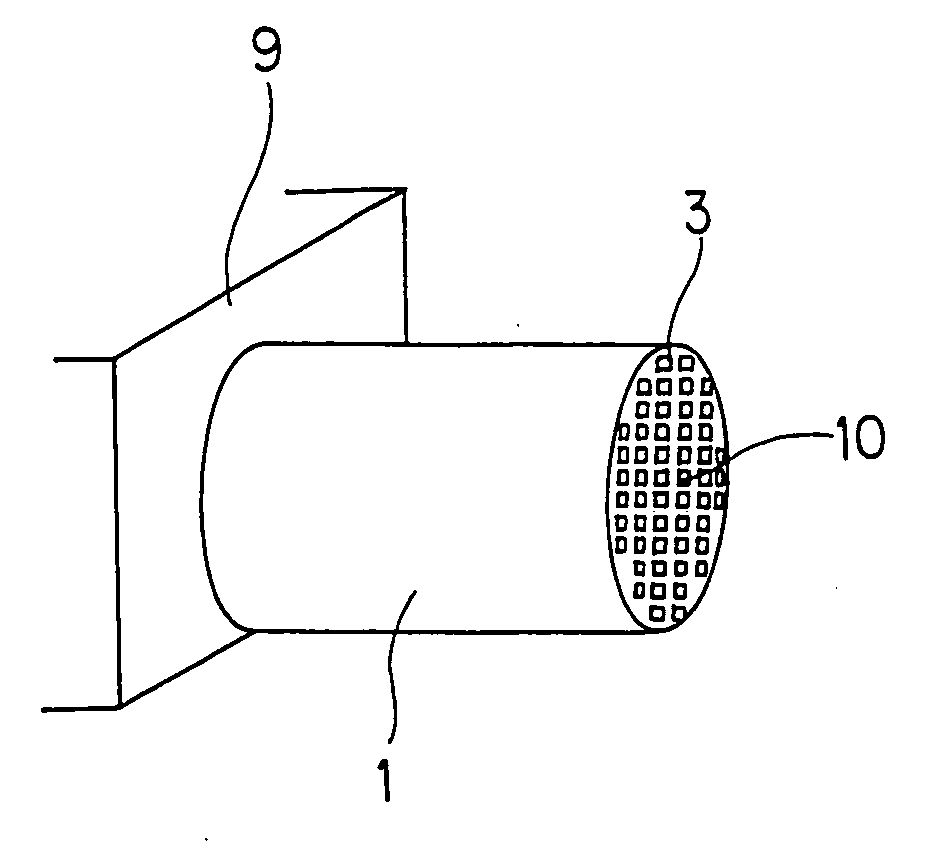
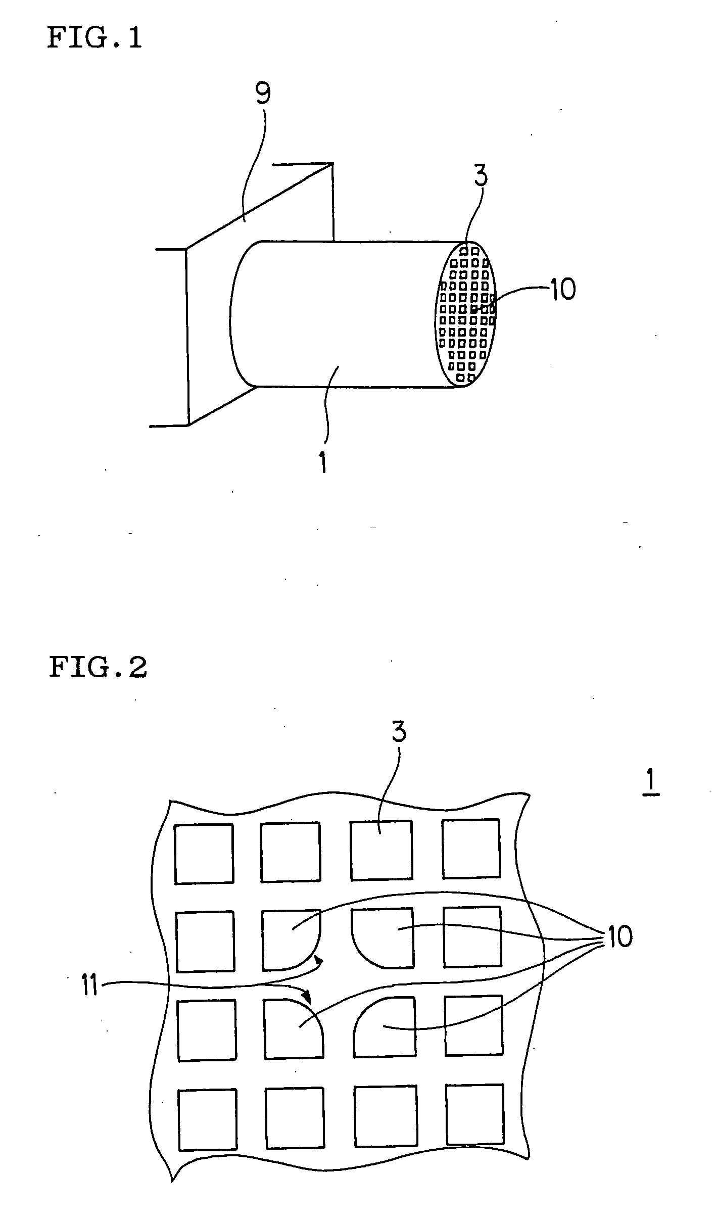
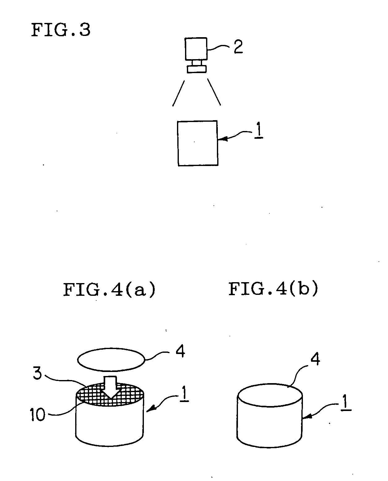
[0026] Embodiments of a method of manufacturing a ceramic honeycomb structure of the present invention, and the ceramic honeycomb structure will be concretely described hereinafter with reference to the drawings.

[0027] In the method of manufacturing the ceramic honeycomb structure of the present invention, sheets are attached to opposite end faces of a ceramic honeycomb body having a plurality of cells and formed into a honeycomb shape, holes are drilled in positions of the sheets, corresponding to opening parts of the cells, a sealing slurry is charged into the opening parts of the cells in the opposite end faces of the ceramic honeycomb body via the holes, and thereafter the body is fired to manufacture the ceramic honeycomb structure in which the opening parts of the cells are alternately sealed. The ceramic honeycomb body is formed into a shape having at least one reference cell different from the other cells in a shape of the opening part in the end face, and the holes are dri...


PUM

PropertyMeasurementUnit
diameteraaaaaaaaaa
shapeaaaaaaaaaa
widthaaaaaaaaaa

Abstract

A method of manufacturing a ceramic honeycomb structure of the present invention, comprising the steps of: stamping sheets onto opposite end faces of a ceramic honeycomb body having a plurality of cells and formed into a honeycomb shape; drilling holes in the sheets at positions corresponding to opening parts of the cells; filling, through the holes, a slurry for sealing into the opening parts of the cells in the opposite end faces of the ceramic honeycomb body; firing the body; and alternately sealing the opening parts of the cells, characterized by comprising the steps of: forming the ceramic honeycomb body into a shape having at least one reference cell different in the shape of the opening part in the end face from the other cells; and drilling the holes in the sheets at the positions corresponding to the opening parts of the reference cell and the other cells with the reference cell taken as a reference point, whereby the ceramic honeycomb structure thus obtained can be manufactured at a low cost, since the cells to be sealed can be easily distinguished, and the holes can be quickly positioned in the drilling step.

Description

TECHNICAL FIELD [0001] The present invention relates to a method of manufacturing a ceramic honeycomb structure, and a ceramic honeycomb structure. The present invention relates more particularly to a method of manufacturing a ceramic honeycomb structure, and a ceramic honeycomb structure in which reference cells different in shapes of opening parts in end faces from other cells are used as reference points in drilling holes in sheets attached to the end faces of a ceramic honeycomb body having a plurality of cells to thereby facilitate the positioning of the holes and in which the holes can be quickly positioned in a drilling step of the ceramic honeycomb body to thereby obtain the ceramic honeycomb structure inexpensively. BACKGROUND ART [0002] Various manufacturing methods have heretofore been known with respect to a ceramic honeycomb structure in which cells in opposite end faces of a ceramic honeycomb body having a plurality of cells and formed into a honeycomb shape are altern...

Claims


Application Information

Patent Timeline
Patent Type & Authority Applications(United States)
IPC IPC(8): B28B11/02B01D39/20B01D46/00B01D46/24B28B11/00B28B11/08C04B38/00F01N3/022
CPCB01D39/2068B01D46/0001B01D46/2451B01D46/2466Y10T428/24149B01D2046/2492B01D2275/206B28B11/006Y10T156/1057B01D46/247B01D46/2484
Inventor FUKUTA, KENOTA, TOMOKO
Owner NGK INSULATORS LTD
Why Eureka
Try Eureka