Infrared gas sensor

a gas sensor and infrared technology, applied in the field of infrared gas sensors, can solve the problems of difficult miniaturization of gas sensor size and easy errors in installation positions, and achieve the effect of small size and stable sensitivity

Inactive Publication Date: 2005-07-28
DENSO CORP
View PDF3 Cites 34 Cited by
  • Summary
  • Abstract
  • Description
  • Claims
  • Application Information

AI Technical Summary

Benefits of technology

[0009] In the above sensor, the resistor and the detection device are disposed on the same substrate, i.e., they are integrated on the same substrate. Accordingly, the arrangement of the resistor, i.e., the light source and the detection device, i.e., the light sensor can be compact. Thus, the dimensions of the gas sensor become smaller.
[0010] Further, since the resistor and the detection device are disposed on the same substrate so that their positioning relationship is predetermined, the positioning accuracy between the light source and the light sensor can be improved, compared with a sensor having the light source and the sensor chip individually disposed on different substrates. Thus, the deviation of the sensor sensitivity is reduced.
[0011] Preferably, the reflection member is a concave mirror. In this case, amount of the infrared light reaching the light sensor, i.e., a coefficient of a received infrared light becomes larger with using the concave mirror so that the sensor sensitivity is increased. Further, the deviation of the sensor sensitivity is improved.
[0012] Preferably, the substrate includes a plurality of membranes as a thin portion of the substrate. The resistor and the detection device are disposed on different membranes, respectively. In this case, the resistor and the detection device are thermally isolated from the substrate. Therefore, the infrared light source can emit the infrared light effectively, and further, the infrared light sensor has a large sensor output.
[0014] Preferably, the detection device has a part made of the same material as the resistor. Further, the detection device has a part, which is disposed on the same plane as the resistor. In this case, the manufacturing process can be simplified. Specifically, when the detection device and the resistor are formed of the same material to be disposed on the same plane, both the resistor and the detection device are formed in the same process at the same time so that the manufacturing process is simplified. Thus, the manufacturing cost of the sensor is reduced.
[0015] Preferably, the substrate is a semiconductor substrate, and the resistor and the detection device are disposed on the semiconductor substrate through an insulation film. In this case, the resistor and the detection device are formed with high positioning accuracy by a conventional semiconductor process method. Thus, the gas sensor with high sensor sensitivity can be formed with low cost.

Problems solved by technology

It is difficult to miniaturize the gas sensor size.
The installation positions are easily subject to errors.

Method used


Image

  • Infrared gas sensor
  • Infrared gas sensor
  • Infrared gas sensor

Examples


Embodiment Construction

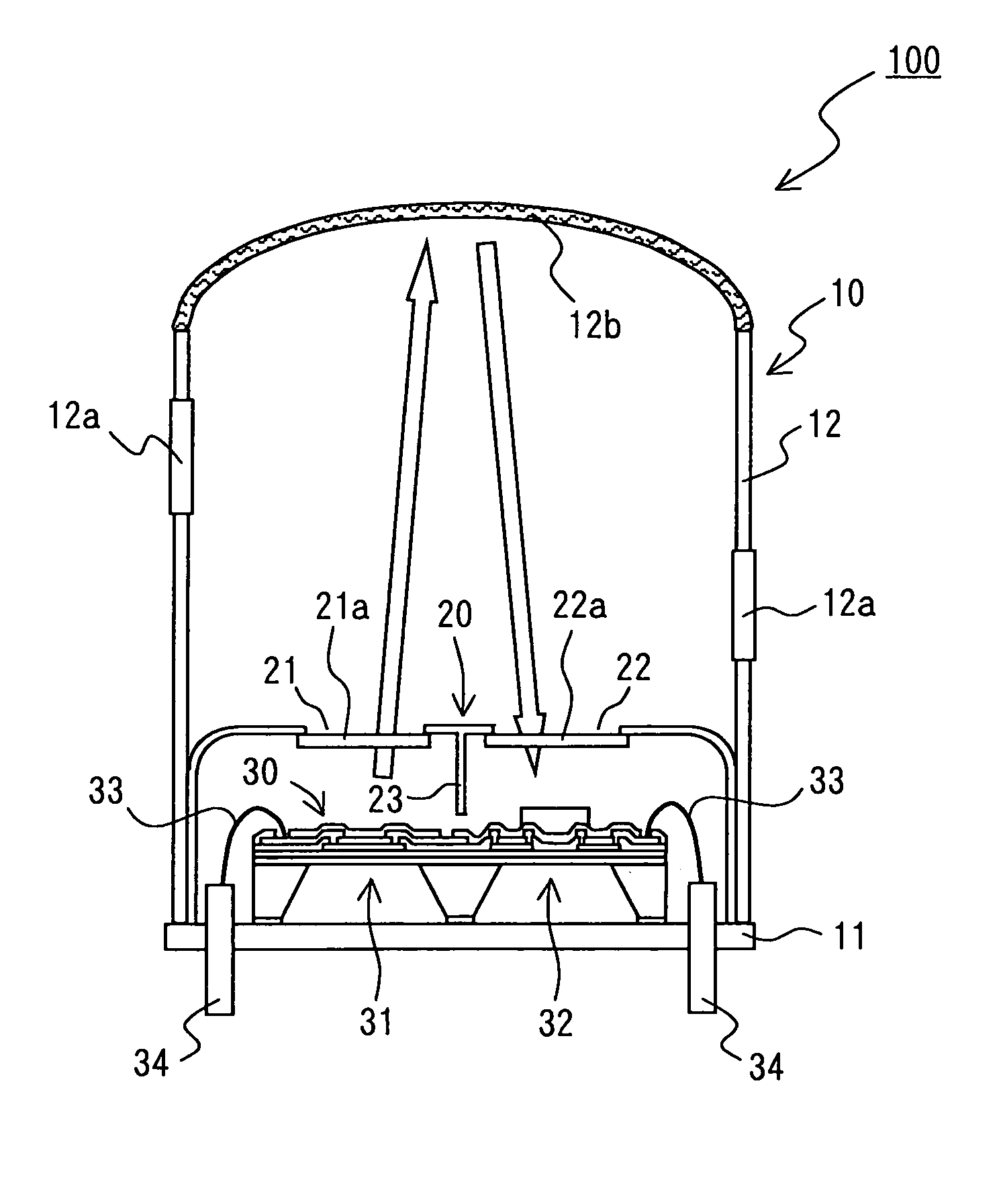
[0022] Embodiments of the present invention will be described in further detail with reference to the accompanying drawings. The present invention is applied to infrared gas sensors having a so-called reflective structure. In such infrared gas sensor, an infrared source radiates infrared light. A reflection member is disposed opposite to the infrared source and reflects the infrared light. An infrared sensor detects the reflected light.

[0023]FIG. 1 schematically shows the configuration of an infrared gas sensor (hereafter referred to as a gas sensor) according to a preferred embodiment of the present invention.

[0024] As shown in FIG. 1, a gas sensor 100 has a reflection member to reflect infrared light and comprises a case 10, a cap 20, and a sensor chip 30. The case 10 is provided so that gas under test can enter. The cap 20 is disposed in the case 10 and limits the infrared light. The sensor chip 30 is disposed in the case 10. The sensor chip 30 is configured to be an integratio...


PUM

PropertyMeasurementUnit
temperatureaaaaaaaaaa
sizeaaaaaaaaaa
infrared light energyaaaaaaaaaa

Abstract

An infrared gas sensor includes: an infrared light source having a resistor for emitting an infrared light by heating the resistor; an infrared light sensor having a detection device for generating an electric signal in accordance with a temperature change of the detection device corresponding to the infrared light in a case where the sensor receives the infrared light; a reflection member for reflecting the infrared light emitted from the light source to introduce the infrared light to the sensor; a casing for accommodating the light source, the light sensor, and the reflection member; and a substrate. The reflection member faces the light source. The resistor and the detection device are disposed on the substrate.

Description

CROSS REFERENCE TO RELATED APPLICATION [0001] This application is based on Japanese Patent Application No. 2004-17427 filed on Jan. 26, 2004, the disclosure of which is incorporated herein by reference. FIELD OF THE INVENTION [0002] The present invention relates to an infrared gas sensor. BACKGROUND OF THE INVENTION [0003] Conventionally, for example, there is known the infrared gas sensor as disclosed in Japanese Patent Application Publication No. H9-184803. This infrared gas sensor comprises an infrared source, an infrared sensor to detect infrared light, and a reflection member disposed opposite to the infrared source to apply the reflected infrared light to the infrared sensor, all contained in the same case. [0004] The infrared gas sensor (hereafter referred to as the gas sensor) provides a light source (infrared source) opposite to a concave reflecting mirror (reflection member). A light receiver (infrared sensor) is provided at or near a position to converge a flux of reflect...

Claims


Application Information

Patent Timeline
Patent Type & Authority Applications(United States)
IPC IPC(8): G01J1/02G01N21/03G01N21/35G01N21/3504H01L27/14H01L27/144
CPCG01N21/3504G01N21/0303
Inventor YOKURA, HISANORISUZUKI, YASUTOSHIYOSHIDA, TAKAHIKO
Owner DENSO CORP
Why Eureka
Try Eureka