Tunable bulk acoustic wave mems microresonator

a bulk acoustic wave and microresonator technology, applied in piezoelectric/electrostrictive device details, generators/motors, piezoelectric/electrostrictive devices, etc., can solve the problem of unsuitable production on an integrated circuit, difficult to exceed the quality factor of an integrated inductance, and added into the integrated circui

a bulk acoustic wave and microresonator technology, applied in piezoelectric/electrostrictive device details, generators/motors, piezoelectric/electrostrictive devices, etc., can solve the problem of unsuitable production on an integrated circuit, difficult to exceed the quality factor of an integrated inductance, and added into the integrated circui

US20050162040A1Inactive Publication Date: 2005-07-28COMMISSARIAT A LENERGIE ATOMIQUE ET AUX ENERGIES ALTERNATIVES

Image

  • Tunable bulk acoustic wave mems microresonator
  • Tunable bulk acoustic wave mems microresonator
  • Tunable bulk acoustic wave mems microresonator

Examples


Embodiment Construction

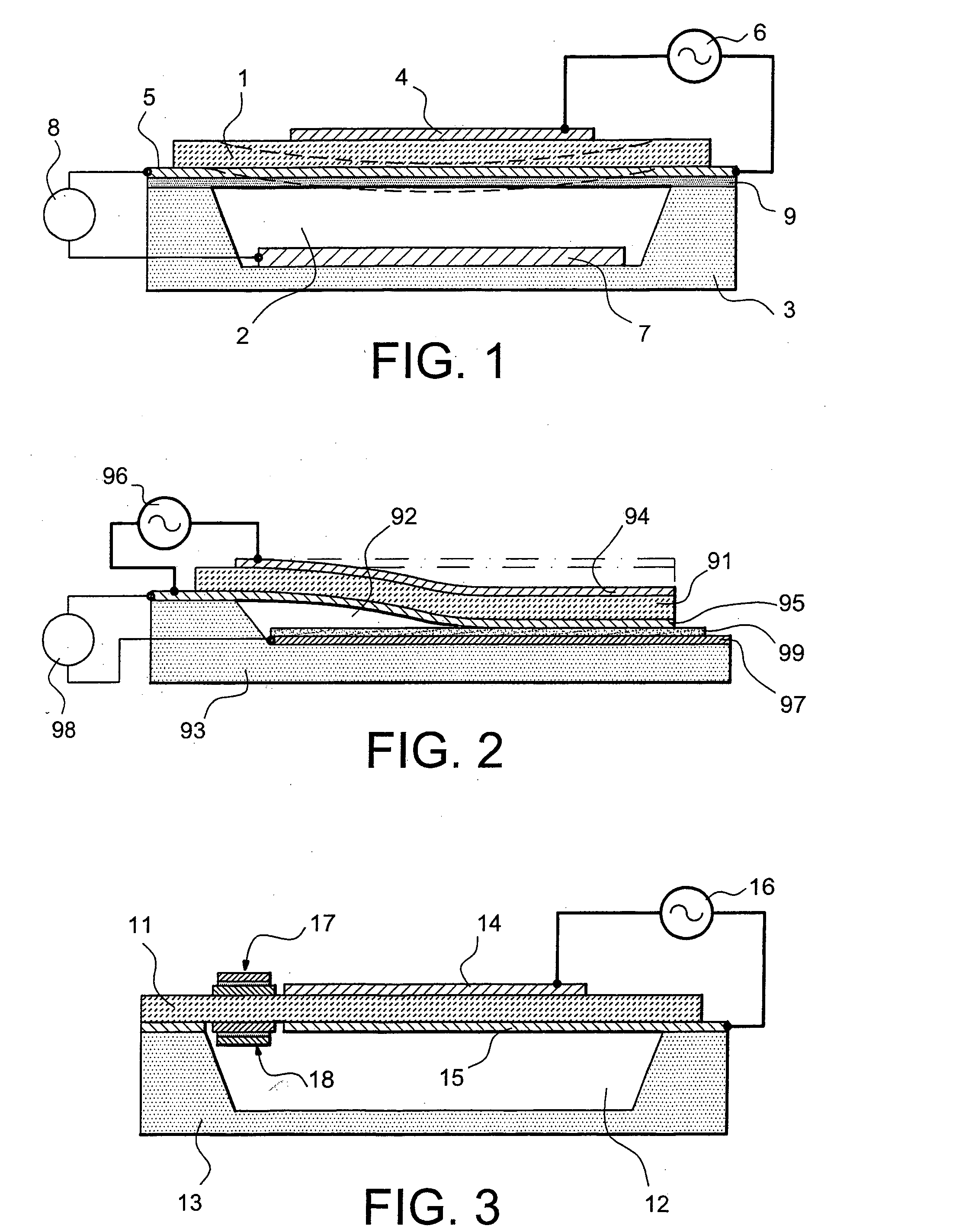
[0035] The following description applies to three variant embodiments of the invention.

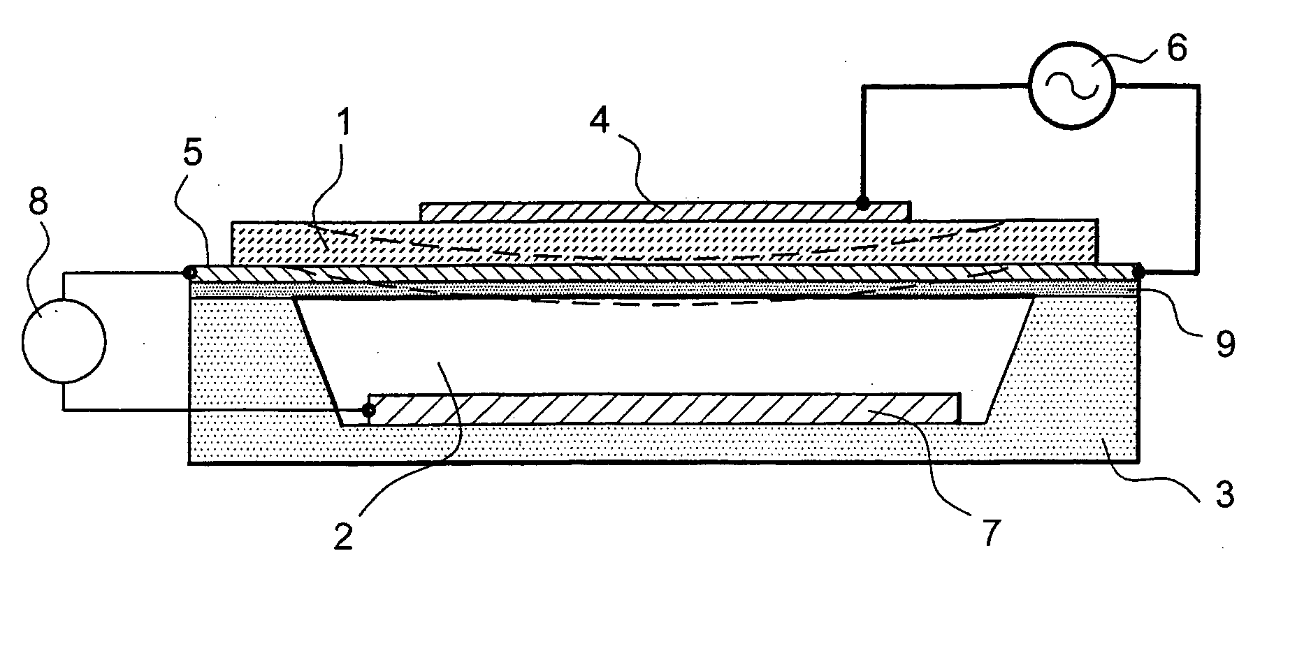
[0036] According to the first variant, the limiting conditions of the resonator are modified by applying a mechanical stress to the beam forming the resonator. The mechanical stress may be the result of an electrostatic force causing bending of the beam, with or without modification to its end embedment. The mechanical stress may also be the result of a thermal bimetallic strip type effect causing pure compression effect (in the case of a double bimetallic strip) or a combined bending moment and compression (for a single bimetallic strip). The mechanical stress may also be the result of a piezoelectric stress introduced by excitation of the resonator itself (for example, deformation of the resonator in the direction of its length or its thickness).

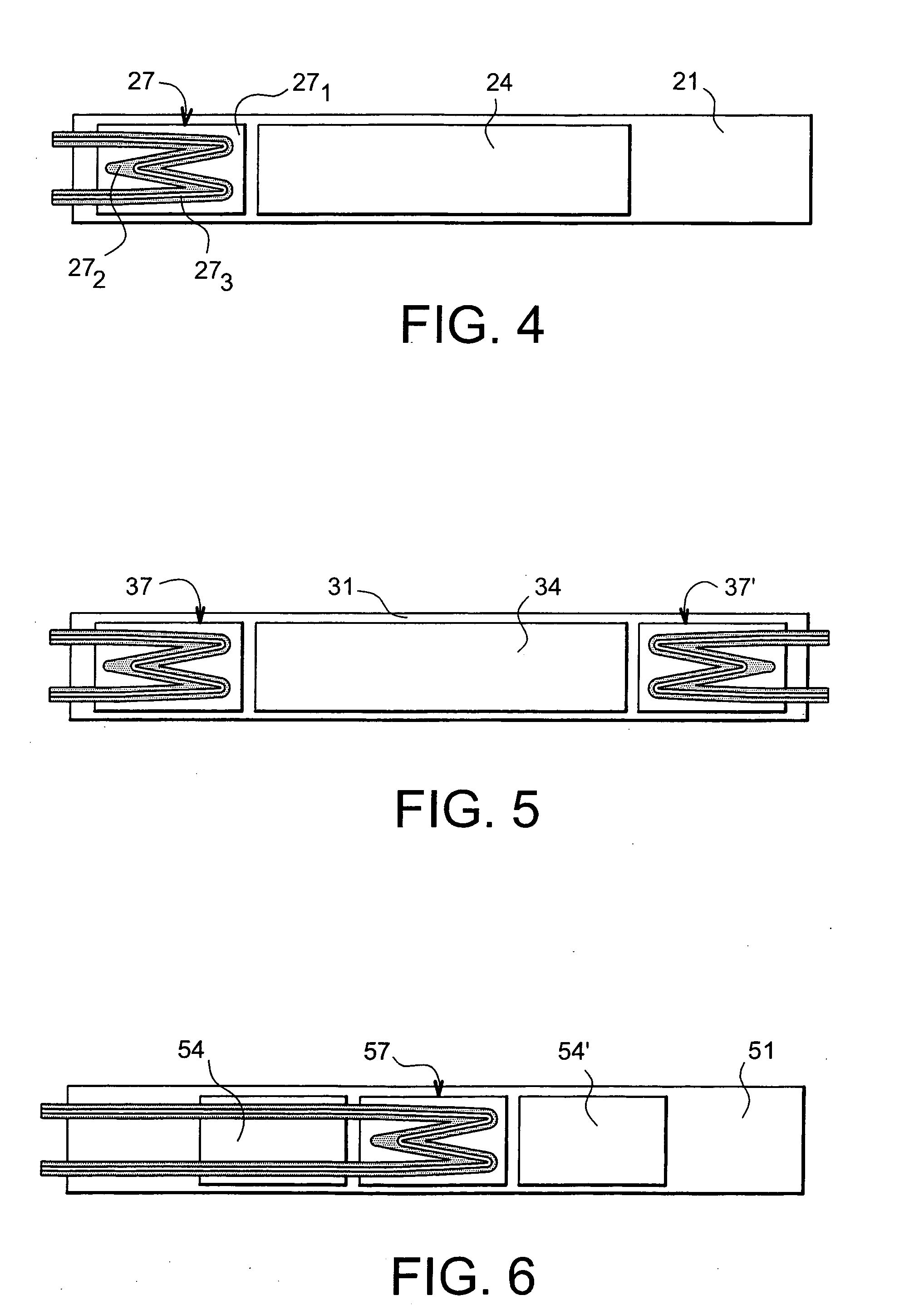
[0037] According to the second variant, the resonator limiting conditions are modified by applying a variable load to the resonator. The variable load...


PUM


Abstract

A suspended film bulk acoustic micro-resonator that includes a beam made of a piezoelectric material fixed to a support and sandwiched between excitation electrodes. The resonator also includes a mechanism modifying limiting conditions of the resonator composed of the excited beam to modify the micro-resonator resonant frequency.

Description

TECHNICAL DOMAIN [0001] This invention relates to a tuneable MEMS (Micro-Electro-Mechanical System) film bulk acoustic micro-resonator. STATE OF PRIOR ART [0002] Several filtering levels are necessary, for example in a transmission-reception system for mobile communications: the antenna output as a band or rejection filter, etc. At the moment, two main solutions are used to make RF filters: [0003] SAW (Surface Acoustic Wave) components that give excellent results but cannot be added into integrated circuits directly; [0004] RLC circuits that can be integrated but for which the characteristics are mediocre considering the performances of each component, particularly the inductance (it is difficult for the quality factor of an integrated inductance to exceed 30). [0005] A third line of research appears, based on the use of mechanical Film Bulk Acoustic Resonators (FBARs). These resonators may be integrated and provide high quality factors (more than 1000). Consequently, these are usef...

Claims


Application Information

Patent Timeline
28 Jul 2005
Publication
US20050162040A1
IPC
B81B3/00; H03H9/17; H03H9/24
CPC
H03H9/172; H03H2009/241; H03H9/173
Inventors
ROBERT, PHILIPPE