Organic light emitting diode with improved light emission through the cathode

a light-emitting diode and organic technology, applied in the direction of discharge tube/lamp details, organic semiconductor devices, discharge tubes, etc., can solve the problems of affecting the aperture ratio and operation stability of the aperture ratio, the inability to easily implement more complex pixel drive circuitry, and the inability to achieve the aperture ratio and operation stability. , the effect of reducing the drive voltag

Active Publication Date: 2005-07-28
GLOBAL OLED TECH
View PDF3 Cites 59 Cited by
  • Summary
  • Abstract
  • Description
  • Claims
  • Application Information

AI Technical Summary

Benefits of technology

[0020] f) the plurality of the hole-injecting layers being configured to reduce the drive voltage, and the reflectivity of the anode, the transparency of the cathode, and the thickness of the organic layers between the electrodes being selected to change the internal reflection of light...

Problems solved by technology

About 80% of generated light is not available for viewing due to losses in wave-guiding modes in glass, ITO and organic layers.
To compensate for the reduced average brightness level, the drive current is increased subjecting the display to increased risk of operational degradation.
It follows that more complex pixel drive circuitry cannot be readily implemented without further compromising aperture ratio and operation stability.
However...

Method used


Image

  • Organic light emitting diode with improved light emission through the cathode
  • Organic light emitting diode with improved light emission through the cathode
  • Organic light emitting diode with improved light emission through the cathode

Examples


example 1

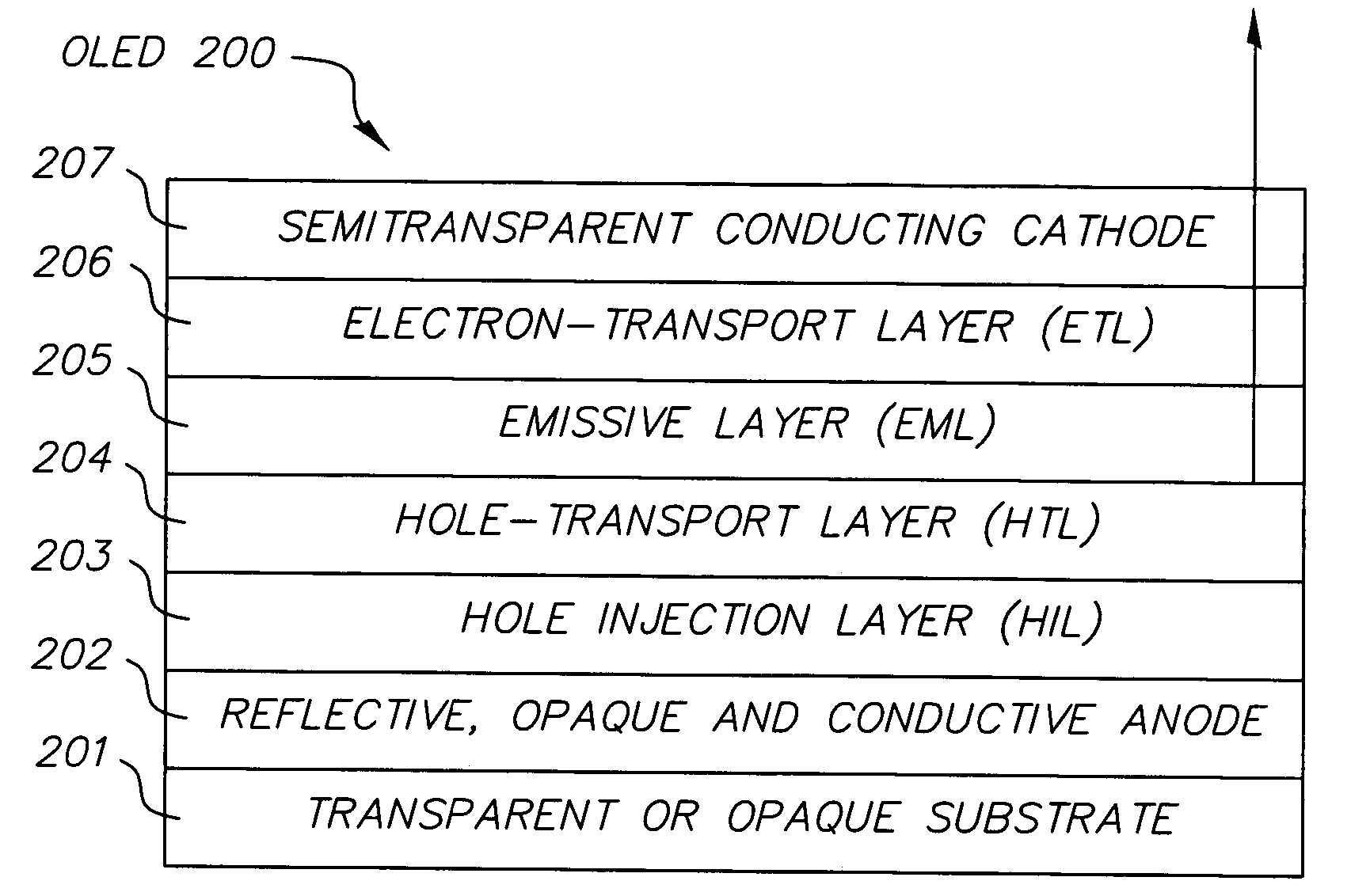
[0060] Ag layer, 80 nm thick, to function as the reflective anode was deposited on several glass substrates. On these surfaces prior art OLEDs each having a separate single layer HIL were fabricated. These OLEDs have an identical 200 nm NPB HTL, a 60 nm Alq EML / ETL, a reflective semitransparent, 14nm thick MgAg cathode. The layer structure and performance of the diodes are presented in Table 2

TABLE 2Drive voltageEfficiencyAVIRHalf-lifeOLEDHIL(V)(cd / A)(mV / h)(hr)1A CFx 1 nm8.63.6320061EMoOx 2 nm9.14.15280

The OLEDs each having a different HIL exhibit comparable drive voltage and efficiency, although the OLED 1A having the single-layer CFx HIL shows slightly lower drive voltage and efficiency than the OLED 1B having the single-layer MoOx HIL. The major difference between them is in the operational stability. The OLED 1E exhibit much lower AVIR and significantly longer lifetime and when compared with the OLED 1A, which is otherwise identical in structure. Thus MoOx as a hole injection ...


PUM


Abstract

Top-emitting organic light-emitting diode devices include a reflective, opaque, and conductive anode layer including a metal or metal alloy or both formed over a transparent or an opaque substrate, a plurality of hole-injecting layers including a bilayer structure having a layer including an oxide and a layer including a fluorinated carbon disposed over the reflective, opaque, and conductive anode, a plurality of organic layers formed over the plurality of hole-injecting layers and including an emissive layer having electroluminescent material and a reflective, semitransparent and conductive cathode include a metal or metal alloy or both provided over the plurality of organic layers, and the plurality of the hole-injecting layers being configured to reduce the drive voltage, and the reflectivity of the anode, the transparency of the cathode, and the thickness of the organic layers between the electrodes being selected to change the internal reflection of light.

Description

CROSS REFERENCE TO RELATED APPLICATIONS [0001] Reference is made to commonly assigned U.S. patent application Ser. No. 10 / 347,013 filed Jan. 17, 2003 by Pranab K. Raychaudhuri et al, entitled “Organic Light-Emitting Diode (OLED) Display With Improved Light Emission Using a Metallic Anode”, commonly assigned U.S. patent application Ser. No. 10 / 346,424 filed Jan. 17, 2003 by Yuan-Sheng Tyan et al, entitled “Microcavity OLED Devices”, and commonly-assigned U.S. patent application Ser. No. ______ (Docket No. 87490) filed concurrently herewith, by Joseph K. Madathil et al, entitled “Organic Light Emitting Diode With Improved Light Emission Through the Substrate”, the disclosures of which are herein incorporated by reference.FIELD OF THE INVENTION [0002] The present invention relates to a top-emitting organic light emitting diodes (OLEDs), which use a semitransparent metallic cathode. BACKGROUND OF THE INVENTION [0003] Organic electroluminescent (OEL) device, alternately known as organic ...

Claims


Application Information

Patent Timeline
IPC IPC(8): H01L51/50H01L51/52H05B33/00H05B33/14
CPCH01L51/5088H01L51/5221H01L2251/558H01L2251/5315H01L51/5265H10K50/17H10K50/828H10K50/852H10K2102/3026H10K2102/351
Inventor MADATHIL, JOSEPH K.RAYCHAUDHURI, PRANAB K.
Owner GLOBAL OLED TECH
Why Eureka
Try Eureka