Liquid leakage sensor and liquid leakage detecting system

a leakage sensor and liquid leakage detection technology, which is applied in the field of liquid leakage sensors and liquid leakage detection systems, can solve the problems of leaking liquid over the upper surface of the holder, the reliability of the liquid leakage detection system is very improved, and the leakage liquid cannot be resolved. the effect of accurate installation of each sensor

Active Publication Date: 2005-07-28
TOYOKOKAGAKU +1
View PDF4 Cites 26 Cited by
  • Summary
  • Abstract
  • Description
  • Claims
  • Application Information

AI Technical Summary

Benefits of technology

[0029] Accordingly, when plural leakage sensors are installed into a control system and connected commonly each other with external outputs at each given group unit, it is enabled for only one operator to accurately install each sensor at the specified spatial position in a short time, and then verify each installation conditions of the respective sensor without searching over a floor surface in order to identify the warning display attached to a conventional sensor. Thus, a reliability of the liquid leakage detecting system can be very improved.
[0030] Further, in the liquid leakage sensor and the liquid leakage detecting system of the present invention, no parent devices of a system are required. Even when a repeater system for the external outputs provided from each sensor is broken out, it is enabled for the maintenance of a plant system to normally detect a leakage condition based on normally functioning sensors and issue a warning sound in an audio frequency. Therefore after detecting a leaking liquid under normally functioning sensors, it is enabled for the maintenance operator to accurately specify the leaking position through the warning sound in the audio frequency and distinguish the activated sensor from other non-activated sensors installed outside of a specified spatial distance and uniquely identify the installation position of the error activated sensor. According to these merits provide

Problems solved by technology

However, since the number of joints connecting these pipes is very numerous, there are many cases in which a liquid is leaked from these joints.
So that it takes a long time for the leaking liquid to diffuse over the upper surface of the holder.
Consequently, the following problems cannot be resolved, that is, a small amount of a leaking liquid cannot be detected at all, or too many times are wasted until a detection of a bit of a liquid is started.
After issuing the warning signal related to the plural leakage sensors, a maintenance problem of a system in a plant occurs, that is, an operator cannot identify quickly where is the error-activated sensor in order to spatially access and repair the abnormal condition among commonly connected plural sensors.
Furthermore, from a view point of the environmental working-conditions, liquid leakage sensors are generally installed at the lowermost portion of a system such as a floor surface, or a liquid storing pan, etc. and various system components are placed at an upper space of the system, therefore, another maintenance problem also occurs in which a light emitting-type alarm display-means such as LED, etc. attached to the liquid leakage sensor itself is functioning very difficult to visually recognize the location of an error-activated sensor among plural sensors, and it is generally difficult to identify easily the location of a leak-activated sensor through the displ

Method used


Image

  • Liquid leakage sensor and liquid leakage detecting system
  • Liquid leakage sensor and liquid leakage detecting system
  • Liquid leakage sensor and liquid leakage detecting system

Examples


embodiment 1

[0068] A liquid leakage detecting system of the present invention will be explained with reference to FIGS. 1 to 6 in a following application for a coating and developing equipment of a semiconductor wafer (hereinafter called a wafer).

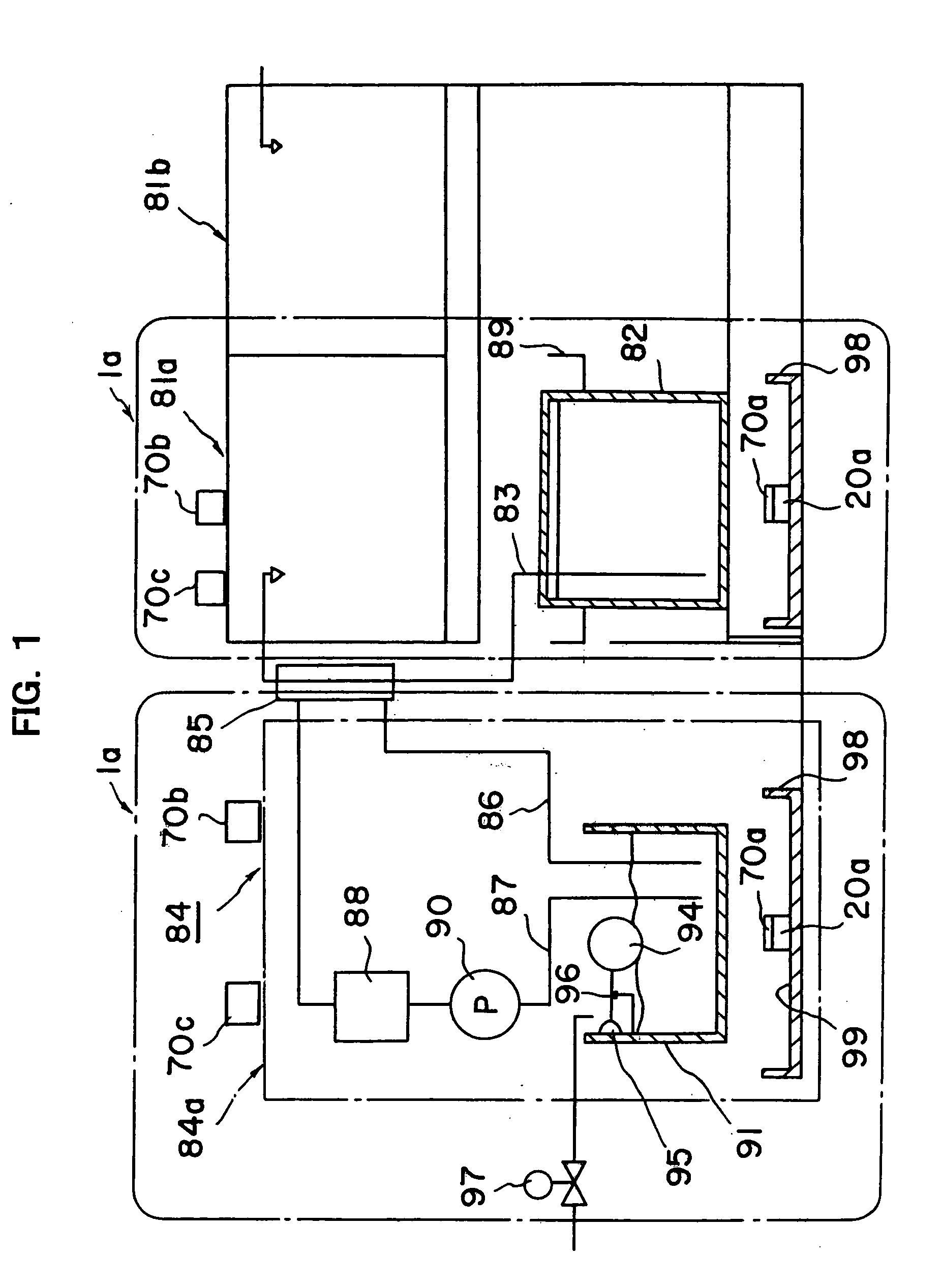
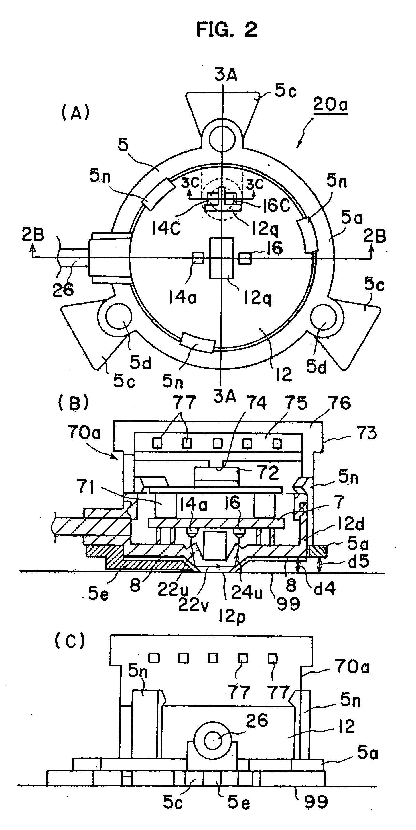
[0069] At first, FIG. 1 shows an embodiment of a liquid leakage detecting system 1a of the present invention wherein a detecting portion of a leaking liquid (a sensing portion of a leaking liquid) 20a is installed in the liquid leakage detecting system 1a and integrally formed with a liquid leakage sensor 20a and a warning means 70a including a sound producing means 72. The detecting portion 20a is comprised at least one liquid leakage sensor including at least one detecting portion contactable with a leaked liquid through a gas layer or a leaking-liquid permeable layer. (In FIG. 1, the detecting portion is made from an optical detecting portion including at least one optically reflecting boundary plane. It can also be made from an electrical detectin...

embodiment 2

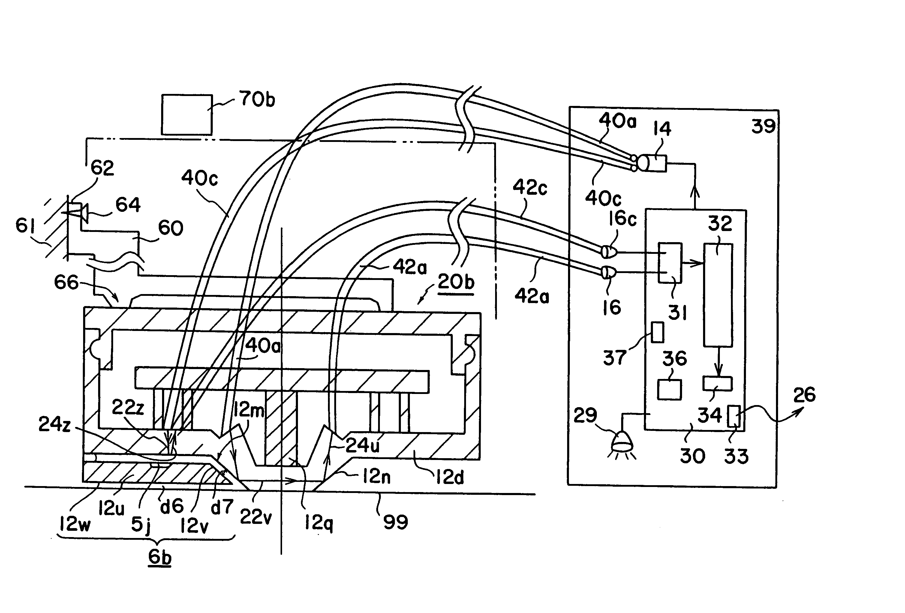
[0123] FIGS. 7 to 9 related to FIGS. 1 to 6 illustrate another embodiment of liquid leakage detecting systems 1b and 1c according to the present invention where the leakage detecting portion (liquid leakage sensor portion) is divided separately into a liquid leakage sensor head 20b and a warning means 70b including a sound producing means. While like components are denoted by like numerals as those of the previous embodiment, in the liquid leakage detecting system 1b of FIG. 7, the liquid leakage sensor 20b and the warning means 70b placed some distance apart constitute an explosion-proof type system 1b for detecting a leakage wherein signals are communicated through wireless means, and in the liquid leakage detecting system 1c, the liquid leakage sensor 20b and the warning means 70b placed some distance apart constitute an explosion-proof type system 1c for detecting a leakage wherein signals are communicated through wired means.

[0124] Further, in the explosion-proof leakage detec...


PUM


Abstract

Among plural liquid leakage sensors placed at the lowermost portion of a system such as a floor surface, a leaked liquid storing portion, etc., an error-activated location of the sensor can be easily identified uniquely when the sensor is detecting any abnormality. In a liquid leakage detecting system including at least one liquid leakage sensor having at least one detecting portion contactable with a leaking liquid through an air layer or a liquid permeable layer, a warning means including a sound producing means is placed within a specified spatial distance from each installation position of said liquid leakage sensor, wherein after detecting any abnormal conditions of said liquid leakage sensor, a warning signal is issued at least in an audio frequency based on said warning means in order to discriminate said error-activated leakage sensor from other non-activated leakage sensors placed outside of said specified spatial distance and uniquely identify said installation position of said activated leakage sensor.

Description

BACKGROUND OF THE INVENTION [0001] 1. Field of the Invention [0002] The present invention relates to improvements of a liquid leakage sensor and a liquid leakage detecting system for detecting a leakage of an electrically conductive liquid such as a water, an acid solution, or an alkaline solution, etc., and a leakage of a liquid having an insulating property such as a super pure water, an organic solution of an alcohol, a thinner, or a benzine, etc. [0003] 2. Background Art [0004] Conventionally, a liquid is supplied through piping in a facility of a factory, etc. However, since the number of joints connecting these pipes is very numerous, there are many cases in which a liquid is leaked from these joints. Therefore, an operator had to monitor a leaking liquid at all times according to the kinds of liquids. As such a conventional liquid leakage sensor, a leakage sensor based on measuring an electrical conductance between electrodes is known for determining a leakage from an impedan...

Claims


Application Information

Patent Timeline
IPC IPC(8): G01M3/16G08B21/00
CPCG01M3/16
Inventor HAYASHIDA, TATEKAZUSHIMAI, FUTOSHIOMATA, YOHEY
Owner TOYOKOKAGAKU
Why Eureka
Try Eureka