Multi-axis joystick and transducer means therefore

a joystick and multi-axis technology, applied in the direction of mechanical control devices, programme control, instruments, etc., can solve the problems of less reliable and robust devices, failure to provide the operator with useful deflection feedback, and high cost, so as to facilitate the use of a single circuit board, reduce noise from ambient vibration, and reduce cost

Inactive Publication Date: 2005-07-28
OBERMEYER HENRY K +1
View PDF99 Cites 167 Cited by
  • Summary
  • Abstract
  • Description
  • Claims
  • Application Information

AI Technical Summary

Benefits of technology

[0143] In accordance with a further aspect of the invention, a noise-canceling element may be provided to reduce noise from ambient vibrations. For example, accelerometers mounted to the base of the device may be used to cancel out spurious signals such as those caused by vehicle vibrations.
[0144] Various aspects of this invention may be utilized in order to reduce in cost and make more compact embodiments of the prior art. For example, the use of mirror elements of this invention in conjunction with the light transducer circuitry and shading means of Hilton et al. may facilitate the use of a single circuit board or monolithic photo transducer. In this example, the mirrors could be stationary and the shading means may be movable or the shading means could be movable and the mirrors stationary. Alternatively, fiber optic or light guide element(s) could be used instead of mirrors in order to reverse the direction of the light paths or to distribute the light from a single source to light paths of suitable orientation and geometry.
[0145] A further embodiment may incorporate a plurality (six, for example) of magnetic flux sensors such as Hall Effect transducers or Giant Magnetic Effect (GME) transducers onto a single printed circuit board which may be movable in multiple degrees of freedom, six for example, relative to a magnetic flux structure which may be established by a single magnet for example. Said embodiment may shield the magnetic flux sensors from ambient magnetic fields by means of a flux conducting magnetic grip or portion thereof, which may provide a flux path (for externally imposed magnetic fields) around the magnetic flux sensors along any required direction. A ferromagnetic pole piece, for example, may be used to direct magnetic flux in a manner which establishes easily measured magnetic flux gradients at the magnetic flux sensors, thus rendering detectable displacement of the flux paths relative to the detectors. The flux may, for example, be directed along three paths with each magnetic flux path intercepting two magnetic flux detectors. The magnetic flux sensors may be located and oriented relative to the flux paths such that the motion sensitive axis, i.e., the direction in which the derivative of the cross products of magnetic flux and the axis of maximum magnetic flux detector sensitivity with respect to displacement are maximum.

Problems solved by technology

The complexity of the prior art designs has resulted in expensive products which may be only affordable for computer aided design and other high value industrial and commercial applications.
The “SpaceOrb®“, which was developed by Spacetec IMC Corporation and marketed as a computer gaming peripheral device for several years during the late 1990's, was ultimately discontinued, perhaps due to its complexity and manufacturing cost relative to its roughly $50 to $100 retail price.
Such a scheme may entail unnecessary complexity of construction and may result in a less reliable and less robust device due to the requirement for movable electrical components requiring flexible connections.
Such devices may essentially be force input devices and may fail to provide the operator with any useful deflection feedback.
The use of such strain gages may be complicated by temperature-induced errors and low gage factors, both of which can add to the difficulty of signal processing and signal shielding.
Furthermore, the allowable strain may be barely perceptible to the operator, and may result in a lack of useful and desirable deflection feedback to the operator.
Furthermore, the low strains may preclude the use of mechanical stops to prevent overloading the strain gages.
Even with a factor of safety, the devices using strain gages may be unsuitable for applications such as computer games, which may often be dropped on the floor by children.
Such devices may be expensive and fragile in comparison to the economical and robust construction of a 6 axis input device built in accordance with the present invention.
The multiple mechanical joints of the prior art may result in a trade-off between precision and cost.
Overall complexity may not be avoided, however, because of the need to shield radio frequency interference and because of interference effects between adjoining inductive springs.
A further disadvantage of the Sundin design may be that the multiple springs could result in an assembly that is subject to unacceptable resonant vibrations if used in association with construction equipment or moving vehicles.
These designs may often be much more complex and expensive than the present invention and may not provide any inherent shielding from ambient magnetic flux
Such a method may be more expensive than the present invention and may lack an intuitive six-axis interface.
The large size of many of the devices built in accordance with prior art may result in unintended and undesirable coupling between the horizontal axis of rotation and the horizontal axis of translation.
Such coupling may require subsequent diagonalization by means of signal processing with a corresponding loss in precision and dynamic range of the device.
Such undesirable coupling may have been difficult to avoid in the prior art because of the expense and technical obstacles, which the required miniaturization of such prior art designs may entail.
Six axis devices of the prior art may be too bulky to incorporate within such a palm rest.
In fact, many six axis input devices of the prior art may have been so bulky that they no longer resemble sticks and may have therefore not even been referred to as “joysticks”.
Currently available devices may be prohibitively high priced for the computer gaming industry and may be too fragile for a typical construction equipment application.

Method used


Image

  • Multi-axis joystick and transducer means therefore
  • Multi-axis joystick and transducer means therefore
  • Multi-axis joystick and transducer means therefore

Examples


Embodiment Construction

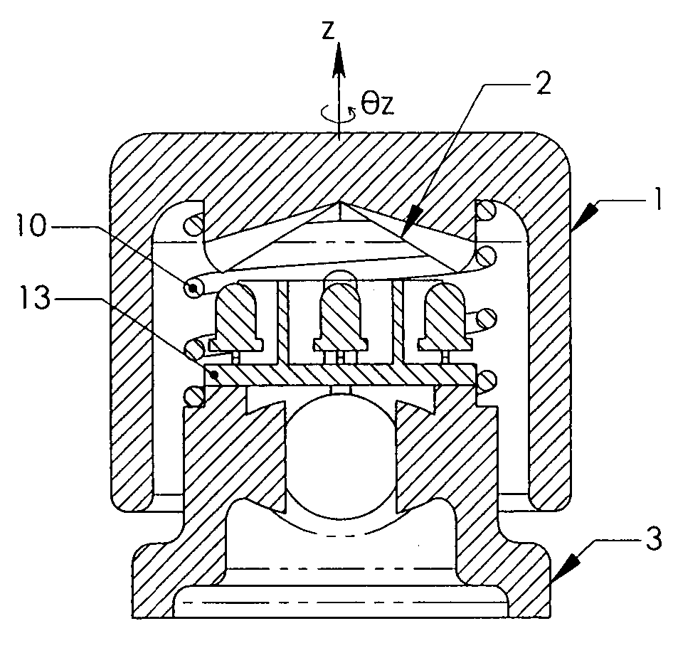
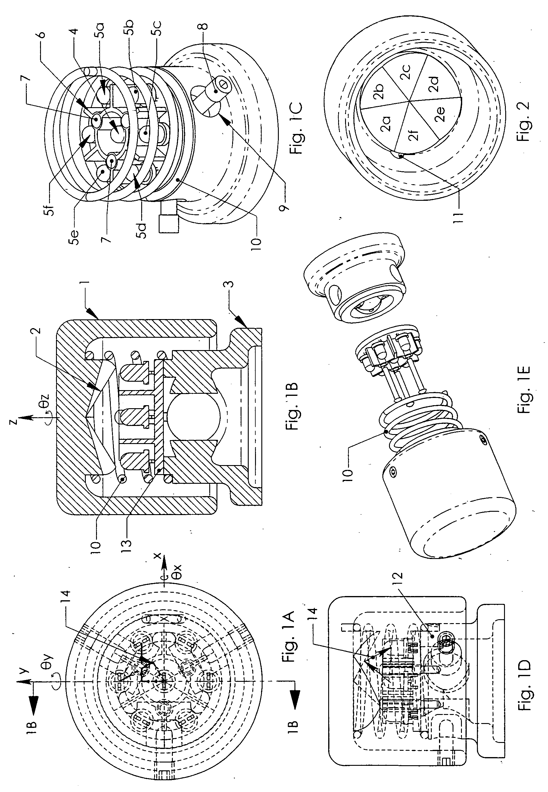
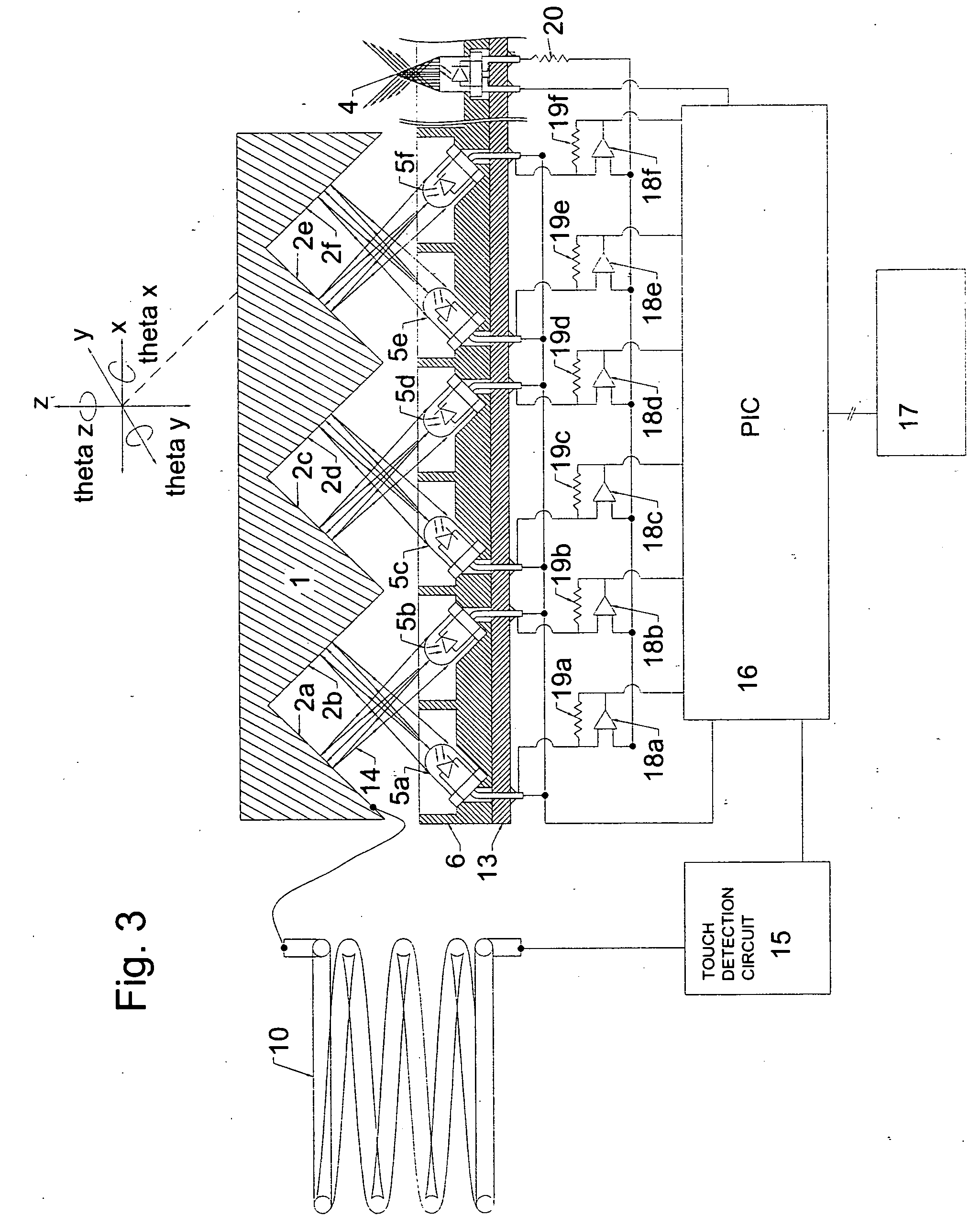
[0264] A multi-axis input transducer apparatus may comprise an at least quinary input element capable of input with respect to at least five frames of reference, a reflective element responsive to radiation from a source capable of emitting radiation eventually incident upon said reflective element and at least one reflected radiation detector responsive to radiation from said reflective element. The term reflection is used broadly to include refraction of said radiation. Referring to FIGS. 1a (plan view), 1b (sectional elevation view), 1c (cutaway perspective view), 1d (elevation view), and 1e (exploded view), a preferred embodiment of a six-axis joystick in accordance with the present invention is shown. Active grip 1 may incorporate reflective facets 2a, 2b, 2c, 2d, 2e, and 2f. Said reflective facets or reflector may be aligned such that each reflects the light from light source or radiation source 4 (which may be a light emitting diode) to a photo detection element or other refl...


PUM


Abstract

The invention relates to improved multi-axis joysticks and associated multi-axis optical displacement measurement means. The displacement measuring means may include one or more light emitters and one or more light detectors, preferably mounted in a planar hexagonal array. The relative position of an adjacent movable reflector assembly can be measured in six degrees of freedom by variations in detected light amplitude. Various ergonomic configurations of six axis joystick embodiments which may be facilitated by the compact design of the transducer means are disclosed. Means for dynamically adjusting coordinate transformations for construction machinery control are also disclosed.

Description

[0001] This application is the U.S. National Stage of International Application No. PCT / US03 / 11614, filed Apr. 14, 2003, and published on Oct. 23, 2003 as WO 03 / 088204 A1, said international application claiming the benefit of, and filed during the pendency of, U.S. Provisional Application Ser. No. 60 / 372,216, filed Apr. 12, 2002, each hereby incorporated by reference.I. TECHNICAL FIELD [0002] The present invention relates to multi-axis input devices such as joysticks for use in, but not limited to, control of computers, control of computer graphics applications in the field of computer-aided design, computer games, and for control of machines such as construction equipment, robotic manipulators, vehicles and the like. The multi-axis optical position transducer herein disclosed may have many other applications, particularly where small size or low cost is important. II. BACKGROUND [0003] Various attempts have been made to develop commercially viable six axis joysticks. [0004] The co...

Claims


Application Information

Patent Timeline
Patent Type & Authority Applications(United States)
IPC IPC(8): G05G9/047G06F3/0338G09G5/08
CPCA63F2300/1043A63F2300/105G05G9/047G06F3/016G05G2009/04759G06F3/0338G05G2009/04755G01D5/285G05B2219/35419G09G5/00G05G9/04737
Inventor OBERMEYER, HENRY KOBERMEYER, FRITZ H.OBERMEYER, LESLIE R.
Owner OBERMEYER HENRY K
Why Eureka
Try Eureka