Element substrate, recording head using the element substrate, and recording apparatus

Inactive Publication Date: 2005-07-28
CANON KK
View PDF3 Cites 7 Cited by
  • Summary
  • Abstract
  • Description
  • Claims
  • Application Information

AI Technical Summary

Benefits of technology

[0042] In order to reduce the difference in time for which a current flows through a heater between a first end and a second end of a nozzle array resulting from delays in a line or changes in the pulse width, a bu

Problems solved by technology

Therefore, an increase in the length of the heater board itself results in an increase in the line length of the logic circuit inside the heater board.
This leads to a characteristic problem with the heater board used in the recording head.
Specifically, even if an integrated circuit technology that achieves a high operatin

Method used


Image

  • Element substrate, recording head using the element substrate, and recording apparatus
  • Element substrate, recording head using the element substrate, and recording apparatus
  • Element substrate, recording head using the element substrate, and recording apparatus

Examples


first embodiment

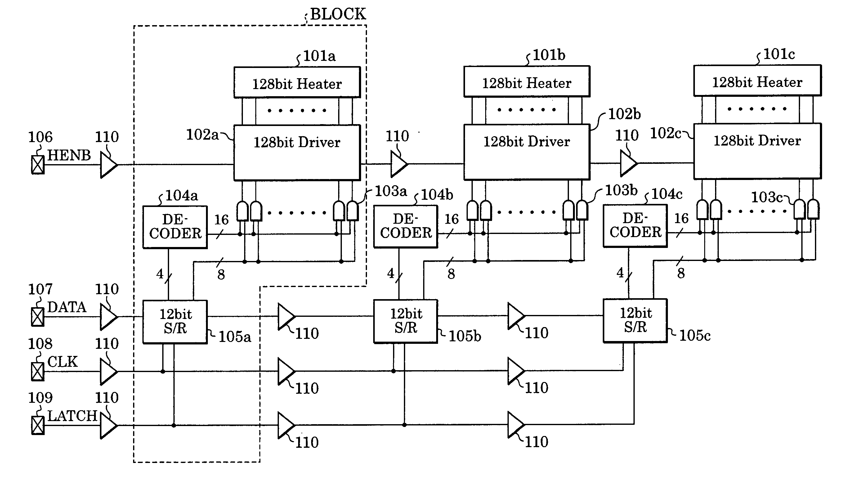
[0083]FIG. 5 is a block diagram showing a heater board (element substrate) of a recording head according to a first embodiment.

[0084] The heater board described in this embodiment includes three blocks arranged on the same heater board at regular intervals, each block including a heater array having 128 heaters.

[0085] First, circuits in a first block among these three blocks are described below. The first block is most adjacent to input terminals 106 to 109. As is apparent from FIG. 5, components are the same among these three blocks. Therefore, the same components bear the same reference numerals with suffixes “a”, “b”, and “c” so as to be distinguished among these three blocks.

[0086] A heater array 101a (represented as 128 bit Heater in FIG. 5) containing 128 heaters included in the first block is connected to a driver array 102a (represented as “128 bit Driver” in FIG. 5) containing the same number of drivers as heaters. These drivers are individually connected to the heaters ...

second embodiment

[0098] There is a case in which a circuit used for data input must be arranged relative to positions of nozzles of a recording head and arranging a block including the circuit ideally relative to positions of pads (input terminals) is impossible. Specifically, for example, two circuits, each described in the first embodiment, are arranged laterally, so that six heater arrays, each having 128 heaters, are arranged on a single heater board.

[0099]FIGS. 6A and 6B are block diagrams showing examples of the structure of the heater board.

[0100] More specifically, in order to apply different data signals, clock signals, and the like to three blocks, for an arrangement shown in FIG. 6A, in which two circuits are arranged according to a block configuration illustrated in FIG. 5 in the first embodiment, mounting is impossible since the pads (input terminals) must be arranged in a central portion 1001 of a heater board 1000.

[0101] Therefore, in order to realize the same orientation with resp...


PUM


Abstract

A buffer circuit for shaping a waveform of a logic signal is arranged where a line for a logic circuit included in a recording-head substrate is divided into substantially equal portions, the line having an unignorable parasitic component due to its increased length. Therefore, the recording-head substrate, a recording head using the recording-head substrate, and a recording apparatus including the recording head are capable of minimizing the adverse effects of parasitic resistance and parasitic capacitance in lines even when the length of a heater array is increased.

Description

BACKGROUND OF THE INVENTION [0001] 1. Field of the Invention [0002] The present invention relates to recording-head substrates, recording heads using the recording-head substrates, and recording apparatuses including the recording heads. In particular, the present invention relates to a recording-head substrate used for discharging ink by, for example, inkjet technologies so as to record information, a recording head using the recording-head substrate, and a recording apparatus including the recording head. [0003] 2. Description of the Related Art [0004] As apparatuses for outputting information used in, for example, word processors, personal computers, and facsimiles, printers for recording information, such as desired text and images, on sheet recording media, such as paper or film, are used. [0005] Various recording technologies in printers are available. Inkjet technologies have increasingly received attention in recent years because the inkjet technologies are capable of record...

Claims


Application Information

Patent Timeline
IPC IPC(8): B41J2/05
CPCB41J2/04541B41J2/04588B41J2/0458B41J2/04543
Inventor SAKURAI, MASATAKA
Owner CANON KK
Why Eureka
Try Eureka