Optical component with holder and manufacturing method thereof

a technology of optical components and holder, which is applied in the direction of lens, manufacturing tools, instruments, etc., can solve the problems of uneven polarization properties, unfavorable use of modules wherein polarization retention is not possible, and uneven internal stress is produced inside the lens, etc., to achieve excellent polarization properties, less internal stress, and accurate determination

Inactive Publication Date: 2005-07-28
NIPPON SHEET GLASS CO LTD
View PDF5 Cites 22 Cited by
  • Summary
  • Abstract
  • Description
  • Claims
  • Application Information

AI Technical Summary

Benefits of technology

[0032] By such mechanical means, the position of the optical element after molding in terms of inside the holder can be accurately determined without using an electronic control means or the like.
[0033] By the present invention as in the above, by appropriately selecting a glass raw material and a holder material based on a relationship of linear expansion coefficients and also appropriately setting the volume of the glass raw material according to the shape of the press-fitting inner circumferential surface and accuracy thereof, an optical component with a holder which has less remaining internal stress, therefore whose polarization properties are excellent, in which chipping or cracks are hardly produced at the edge part of the optical element, and which is excellent in airtightness can be provided. Furthermore, by combining these with a semiconductor optical element, it is also possible to provide a small-sized optical component excellent in reliability.

Problems solved by technology

However, in the method and structure, an uneven internal stress is produced inside the lens finished by molding by a steep point of the projecting portion of the inner circumferential surface of the lens holder.
When an internal stress is being produced inside a transmission optical component such as a lens, polarization properties therefore become uneven, and it cannot be used particularly for a module wherein polarization retention is required.
In addition, as a result of forming the projecting portion, during molding, a part of the glass raw material protrudes outside the molds and can cause chipping.
However, the shape of the lens holder is complicated, and the processing cost is increased.
Moreover, it is necessary to deform the annular projection by an upper metal die for molding, and it is technically very difficult to deform a part of a metal component by an expensive metal mold which is made mainly of a brittle material or ceramic.
On the other hand, in JP H03-237408A as well, a point is formed at the step portion between the retaining portion and inner surface, an uneven internal stress is similarly produced, and this may cause chipping at an edge part of the lens.
However, if a projection and a complicated structure exist on the inner circumferential surface of the lens holder, a problem also exists such that this matching in volume is not easily achieved.

Method used


Image

  • Optical component with holder and manufacturing method thereof
  • Optical component with holder and manufacturing method thereof
  • Optical component with holder and manufacturing method thereof

Examples


example 1

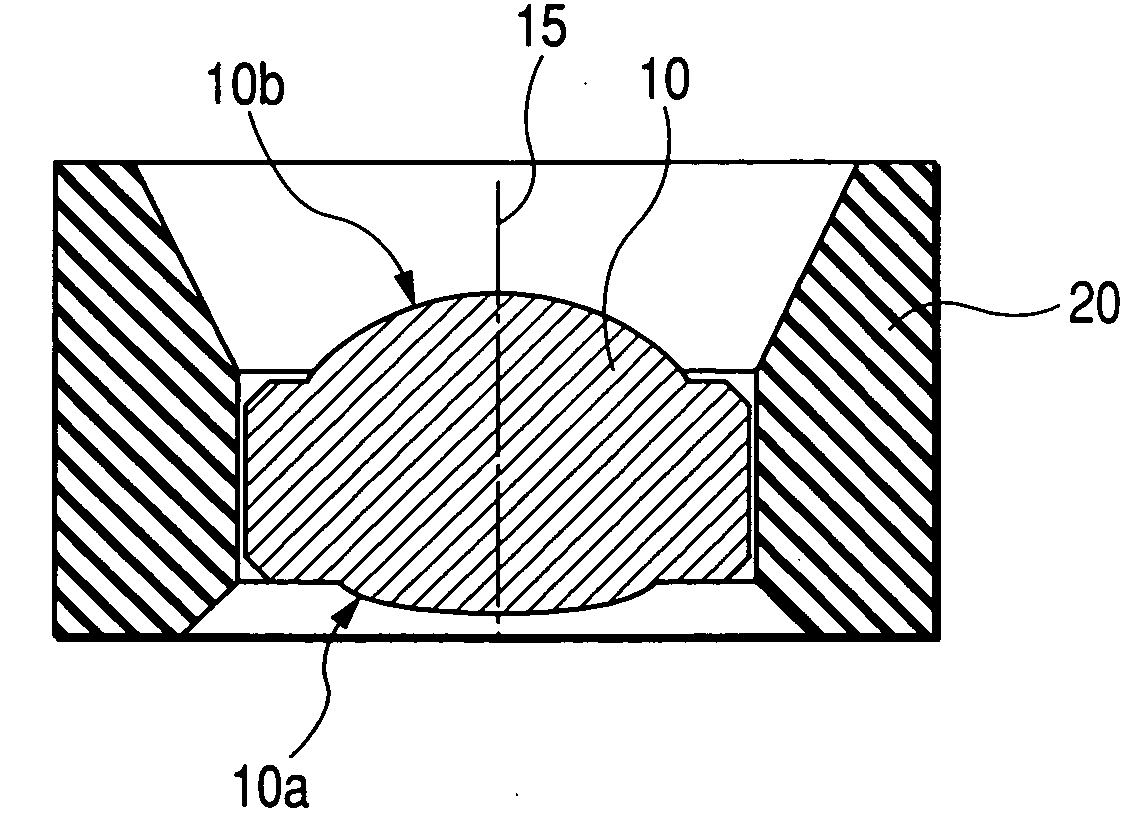
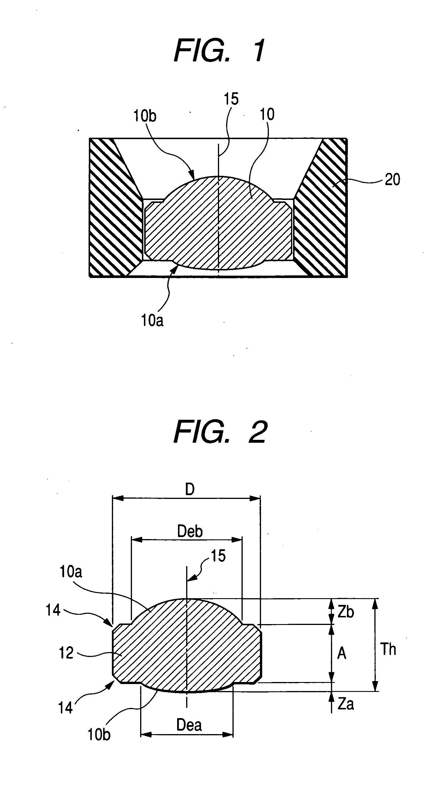
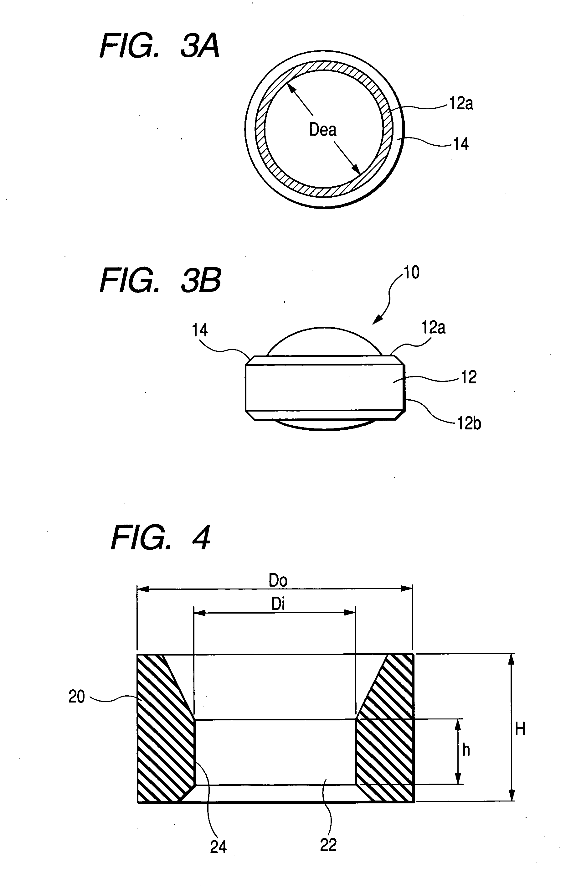
[0087] Hereinafter, a concrete example according to the present invention is shown. A lens shape is basically the same as that shown in FIG. 2 or FIGS. 3A and 3B, and this is fixed to a lens holder in a shape shown in FIG. 4. The lens shape and lens holder shape of the present example will be described in the following.

[0088] For the shape of an aspherical lens, a sag amount Z is expressed by a polynomial expression of a radial distance r from the lens center:

Z=Th+ar2+br4+cr6+dr8, and

aspherical coefficients a, b, c, and d are provided as values shown in Table 1.

[0089] In addition, dimensions and processing tolerances of respective portions of the lens holder are shown in Table 2.

[0090] As a glass raw material for the lens, glass whose linear expansion coefficient is 102×10−7 / ° C. is processed in a globular form and used. As a lens holder material, SF20T of ferritic stainless steel is used. Its linear expansion coefficient is 110×10−7 / ° C.

[0091] In order to fabricate a lens of...

example 2

[0100] In the present example, such an optical component as shown in FIG. 10 wherein a lens 10 having basically the same shape as that of the above-described example 1 has been fixed to a holder 100 was fabricated. Although a lens holder part 120 to which the lens 10 has been fixed has the same structure as that of Example 1, this holder 100 is different in having, at its lower portion, a cylindrical part 122 with a large inside diameter.

[0101] By designing and fabricating such an optical component, as shown in FIG. 11 or FIG. 12, an optical element wherein a semiconductor laser chip 70 and a lens has been integrated can be provided. The chip 70 is bonded onto a base 72, and electrodes and lead wires 74 on the chip are connected. On the surface of this base 72, a straight cylindrical part 122 of the lens holder to which a lens has been fixed as shown FIG. 10 is covered, and a contact point thereof 76 is airtightly sealed by welding or the like. Prior thereto, an inactive gas such a...


PUM

PropertyMeasurementUnit
diameteraaaaaaaaaa
diametersaaaaaaaaaa
temperatureaaaaaaaaaa

Abstract

As means of the present invention, first, on the optical element, a plate-like peripheral edge part which is protruding, while surrounding an effective part having an optical function thereof, outside from the effective part is provided. Furthermore, at a part of the through hole of the holder, a straight cylindrical part is provided. Then, an outer circumference of the peripheral edge part is tightly fitted to an inner circumferential surface of the cylindrical part of the through hole throughout the entire circumference.

Description

BACKGROUND OF THE INVENTION [0001] 1. Field of the Invention [0002] The present invention relates to an optical component with a holder provided by fixing an optical element used in a technical field of optical communications, optical information reading and the like to a holder, and in particular, it relates to an optical component with a holder manufactured by a molding method. [0003] 2. Related Art [0004] Although it is widely known that lenses are used in a technical field of optical communications, optical information reading and the like, most of these lenses are generally used while being previously fixed to lens holders. Although these lens fixing methods are variously provided, in particular, known is a technique of press-fitting a raw-material glass to the inside of a metallic lens holder while simultaneously molding the same in a spherical or aspherical form and integrating the lens and holder (see Japanese Patent Publication No. JP H03-265529A or, Japanese Patent Publica...

Claims


Application Information

Patent Timeline
Patent Type & Authority Applications(United States)
IPC IPC(8): C03B11/08C03B35/00G02B3/00G02B3/04G02B6/32G02B6/42G02B7/02
CPCC03B11/08C03B35/00G02B7/02C03B2215/79G02B6/4206C03B2215/49
Inventor TANAKA, HIROYUKI
Owner NIPPON SHEET GLASS CO LTD
Why Eureka
Try Eureka