[0007] The invention generally relates to material conveying systems and methods that reliably convey selected quantities of material using peristaltic pumps, including microliter volumes of fluidic material. The approaches to reproducibly conveying desired quantities of material described herein readily account for periodic variations that are commonly observed in quantities of material conveyed with peristaltic pumps, and are typically less complex to implement than many pre-existing conveyance techniques. According to certain embodiments, for example, the systems of the invention are configured to effect substantially identical roller disengagement events for each quantity of material conveyed to minimize roller disengagement as a source of variation among conveyed quantities. In certain embodiments, the systems and methods of the invention further provide for the synchronous and accurate conveyance of multiple quantities of material to achieve elevated levels of
throughput. Embodiments of the invention also include methods to minimize the carryover of material between material sites, such as between wells disposed in a multi-well container, to reduce, e.g., the risk of cross-contaminating those sites or conveying inaccurate amounts of material. The invention also provides related
computer program products that can be used to implement the methods and systems described herein.
[0008] In one aspect, the invention provides a material conveying
system. The
system includes at least one
peristaltic pump having a rotatable roller support that supports at least two rollers (e.g., fixed rollers, rotatable rollers, or combinations thereof), and at least one motor that is operably connected to the
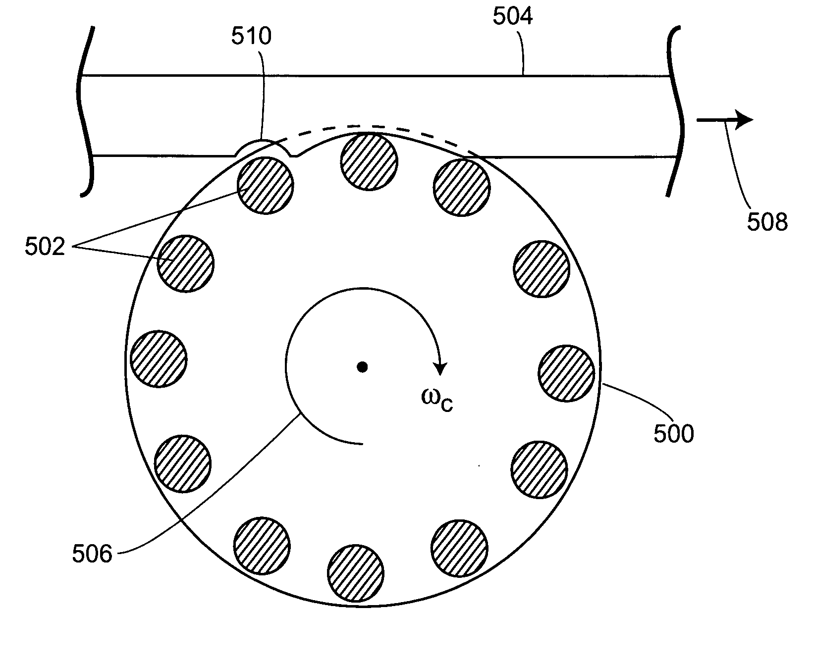
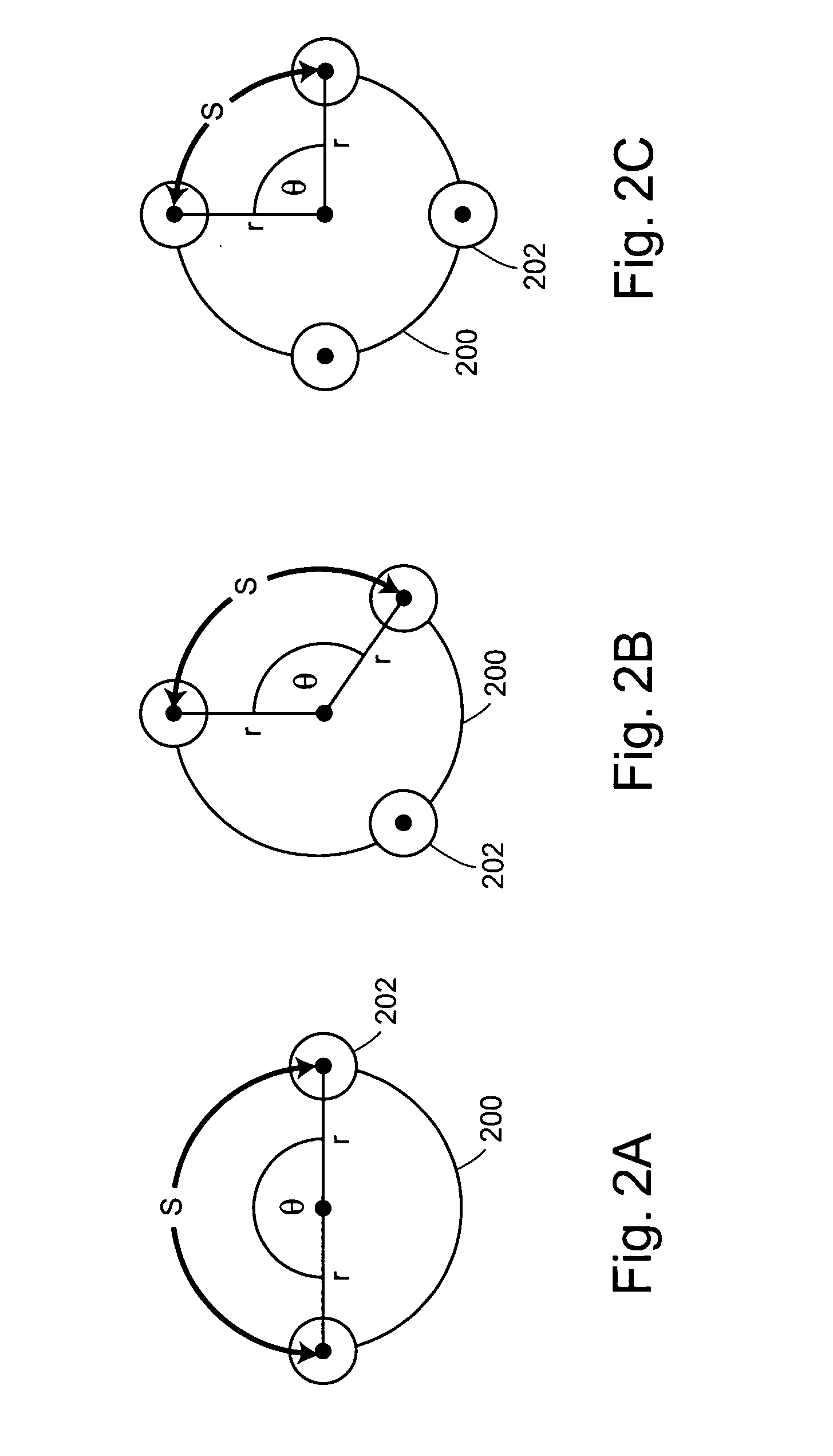
peristaltic pump to rotate the roller support. The system also includes at least one controller that is operably connected to the motor. The controller is configured to effect rotation of at least the roller support in at least one rotational increment that substantially corresponds to an integral multiple of an
angular distance disposed between adjacent rollers supported by the roller support such that when one or more material conduits are operably connected to the
peristaltic pump and the peristaltic pump conveys material through the material conduits, quantities of material that correspond to the rotational increment are conveyed to or from at least one material site (e.g., a material container, a
substrate surface, etc.). Identical rotational increments generally convey substantially uniform quantities of material to or from the material site. Moreover, the rotational increment is typically uncompensated for flow rate characteristics of the system. In some embodiments, the system further includes at least one material conduit that is operably connected to the peristaltic pump. Typically, the controller is configured to effect substantially identical roller disengagements from the material conduit for each conveyed quantity of material to minimize periodic variation among the conveyed quantities of material. Optionally, the system also includes at least one
detector operably connected to the controller. The
detector is configured to detect detectable signals produced at one or more material sites.
[0011] The peristaltic pumps that are included in the material conveying systems of the invention include various embodiments. In some embodiments, for example, the peristaltic pump comprises a multi-channel peristaltic pump. Typically, the peristaltic pump is configured to reversibly convey the quantities of material to or from the material site. In addition, the peristaltic pump typically generates sufficient
material flow rates at least proximal to a terminus of the material conduit to effect non-contact material dispensing from the terminus. Further, the roller support typically supports, e.g., 3, 4, 5, 6, 7, 8, 9, 10, 11, 12, 13, 14, 15, 20, 30, or more rollers. The
moment of inertia of the roller support is generally minimized to prevent a quantity of material from adhering to an external portion of the material conduit when the peristaltic pump conveys material through the material conduit. Moreover, angular distances disposed between pairs of adjacent rollers supported by the roller support are typically substantially equal to one another. For example, adjacent rollers supported by the roller support are generally disposed at most 180° apart from one another. In some embodiments, the roller support is interchangeable with at least one other roller support. In embodiments where the rollers are rotatable, the peristaltic pump optionally includes a gear mechanism that effects rotation of the rotatable rollers when the motor rotates the roller support, e.g., to minimize material conduit wear.
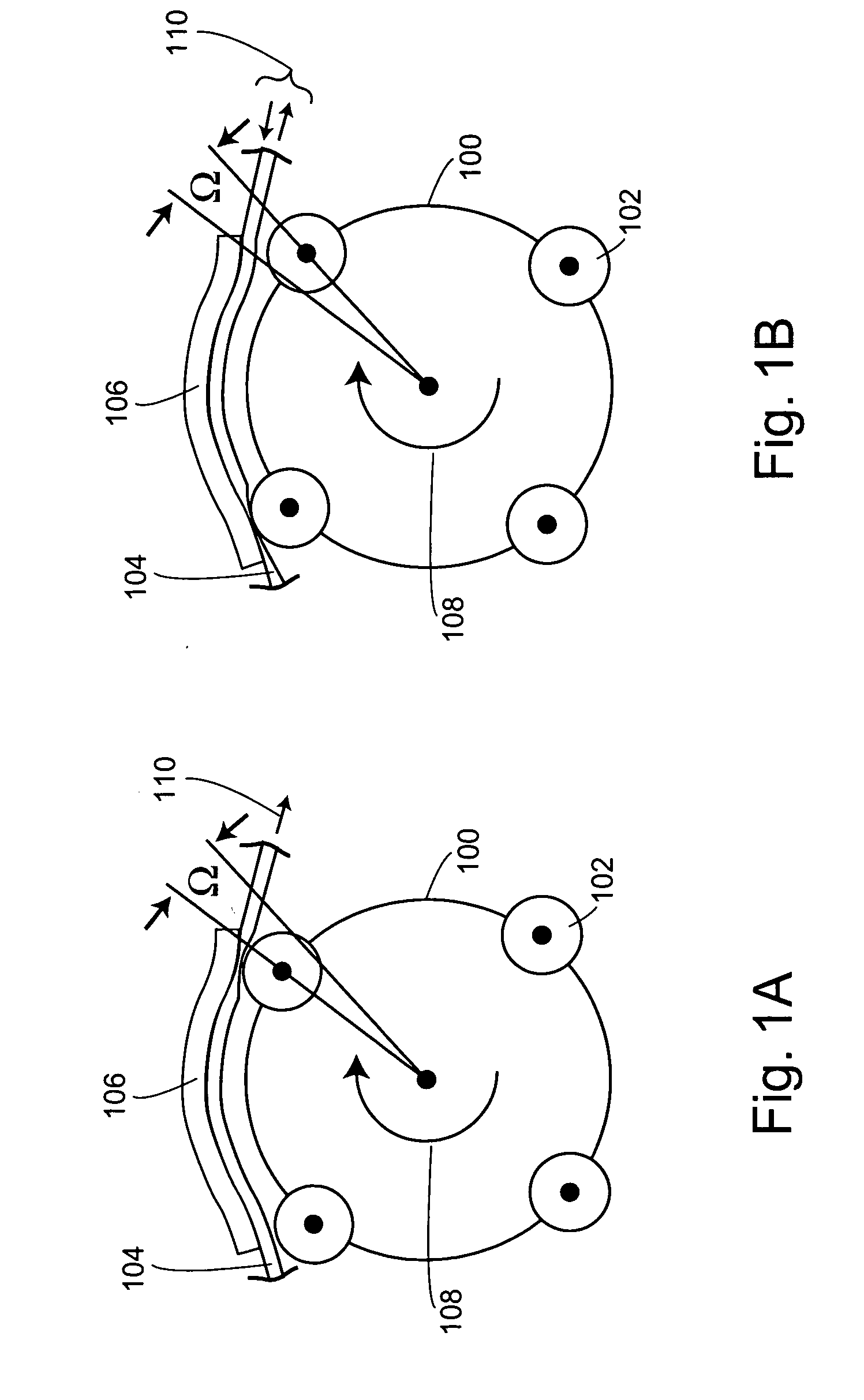
[0013] The controller is generally configured to effect substantially identical roller disengagements from the material conduit for each conveyed quantity of material to minimize periodic variation among the conveyed quantities of material. In embodiments where the rollers are rotatable, the controller is optionally further configured to effect rotation of at least one of the rollers supported by the roller support. In these embodiments, the rollers typically rotate in a direction that is opposite from a direction of rotation of the roller support to minimize material conduit wear. For example, the rollers and the roller support typically rotate at velocities that have substantially equal absolute values. In certain embodiments, the controller effects at least one negative pressure pulse at least proximal to a terminus of the material conduit after effecting rotation of the roller support in the rotational increment to prevent a quantity of material from adhering to an external portion of the material conduit. The
moment of inertia of the roller support is generally minimized to further prevent the quantity of material from adhering to the external portion of the material conduit.
[0021] In another aspect, the invention relates to a method of conveying material. The method includes providing a material conveying system comprising at least one controller that is operably connected to at least one motor that is operably connected to at least one peristaltic pump. The peristaltic pump comprises a rotatable roller support that supports at least two rollers and is operably connected to at least one material conduit. The system is typically automated. The method also includes conveying the material (e.g., a
cell suspension, a
reagent, a buffer, a
solid support suspension, etc.) through the material conduit in which the controller effects rotation of the roller support in at least one rotational increment that substantially corresponds to an integral multiple of an
angular distance disposed between adjacent rollers supported by the roller support such that quantities of material conveyed to or from at least one material site correspond to the rotational increment. The controller typically effects rotation of the roller support such that shearing effects on material (e.g., cells or the like) conveyed in the material are minimized. Typically, the material is conveyed to the material site without the material conduit contacting the material site. The quantities of material generally comprise at least 0.1 μl of the material. In some embodiments, the system further comprises at least one feedback component that is operably connected to the motor, which feedback component effects position
feedback control of the peristaltic pump. The controller generally effects substantially identical roller disengagements from the material conduit for each conveyed quantity of material to minimize periodic variation among the conveyed quantities of material. The rotational increment is generally uncompensated for flow rate characteristics of the system. Identical rotational increments typically convey substantially uniform quantities of material to or from the material site. In certain embodiments, the method further includes effecting at least one negative pressure pulse at least proximal to a terminus of the material conduit with the controller after effecting rotation of the roller support in the rotational increment to prevent a quantity of material from adhering to an external portion of the material conduit.
[0025] In another aspect, the invention provides a method of conveying material to a material site. The method includes providing a material conveying system comprising at least one material conduit, and at least one pump that is operably connected to the material conduit, which pump conveys the material through the material conduit. The material conveying system also includes at least one positioning component that is operably connected to the material conduit, which positioning component moves the material conduit. In addition, the material conveying system also includes at least one controller that is operably connected to the pump and the positioning component. The controller effects the pump to convey the material through the material conduit and the positioning component to move the material conduit. The method also includes conveying the material (e.g., fluidic material, etc.) through the material conduit such that a quantity of the material adheres to a terminal portion of the material conduit, thereby forming an adherent material quantity. In addition, the method also includes accelerating at least the terminal portion of the material conduit towards the material site with the positioning component, and decelerating the terminal portion of the material conduit with the positioning component such that the adherent material quantity is conveyed from the terminal portion of the material conduit to the material site. The material site generally comprises at least one well of a multi-well container. The decelerating step typically comprises ejecting the adherent material quantity from the terminal portion of the material conduit. Typically, the adherent material quantity is conveyed to the material site without contacting the terminal portion of the material conduit and the material site. In some embodiments, the material comprises a
cell suspension and the method minimizes shearing effects on conveyed cells.

