Porous membrane microstructure devices and methods of manufacture

a microstructure device and porous membrane technology, applied in the direction of membranes, filtration separation, separation processes, etc., can solve the problems of poor mechanical support of catalyst material(s), complex and difficult implementation of control of reaction fluid management outside of the reactor, and the tube-type membrane reactor provides poor mechanical support for catalyst material(s). , to achieve the effect of maximizing fluid interaction, high surface-to-volume ratio, and increasing productivity or yield

Inactive Publication Date: 2005-08-04
CORNING INC
View PDF4 Cites 47 Cited by
  • Summary
  • Abstract
  • Description
  • Claims
  • Application Information

AI Technical Summary

Benefits of technology

[0013] The disclosed membrane microstructure devices and methods of manufacturing a membrane microstructure device result in a number of advantages over other microstructure devices and manufacturing techniques known in the art. For example, the unitary construction of the disclosed porous membrane microstructure device provides significant mechanical support for the porous membrane heretofore unrealized in the art. In addition, such construction enables substantially leak-free catalytic and non-catalytic chemical processing within the membrane microstructure.
[0015] Still further advantages are obtained from the micro-scale internal dimensions of the microchannels defined within the disclosed membrane microstructure device. Generally speaking, the micro-scale microchannel dimensions provide high surface-to-volume ratios, which in turn, maximizes fluid interaction with the porous membrane. In those cases where the porous membrane is impregnated with or otherwise supports one or more catalysts, fluid / catalyst(s) contact via the porous membrane is maximized. As a result, increased productivity or yield is realized.

Problems solved by technology

As one of skill in the art readily recognizes, industrialization and parallelization of such tube-type reactors is complicated and difficult to implement.
Moreover, control of the reaction requires complex fluid management outside of the reactor, particularly upstream of the inlet port or ports.
In addition to these shortcomings the structure of tube-type membrane reactors provides poor mechanical support for the catalyst material(s), and is not easily sealed.
Accordingly, leakage from such devices is generally the norm, which significantly adversely effects efficiency.
The microlamination processing techniques and other techniques necessary to manufacture such porous layers is generally cost prohibitive for mass production, and porous membranes manufactured by these techniques have been found to have limited application for chemical processing.
For example, the unitary construction of the disclosed porous membrane microstructure device provides significant mechanical support for the porous membrane heretofore unrealized in the art.

Method used


Image

  • Porous membrane microstructure devices and methods of manufacture
  • Porous membrane microstructure devices and methods of manufacture
  • Porous membrane microstructure devices and methods of manufacture

Examples


Embodiment Construction

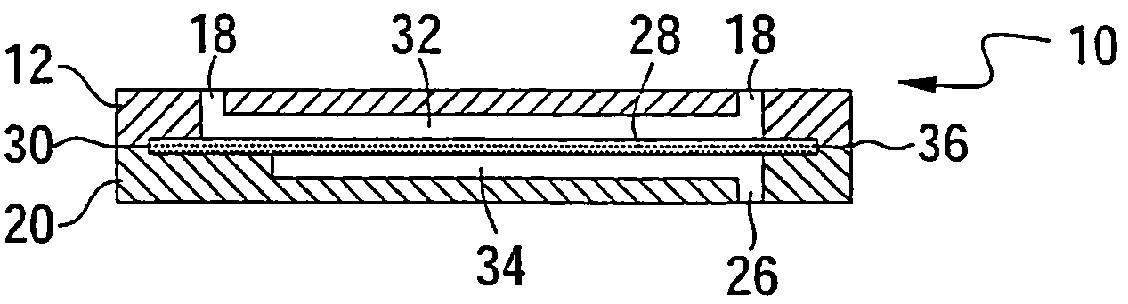
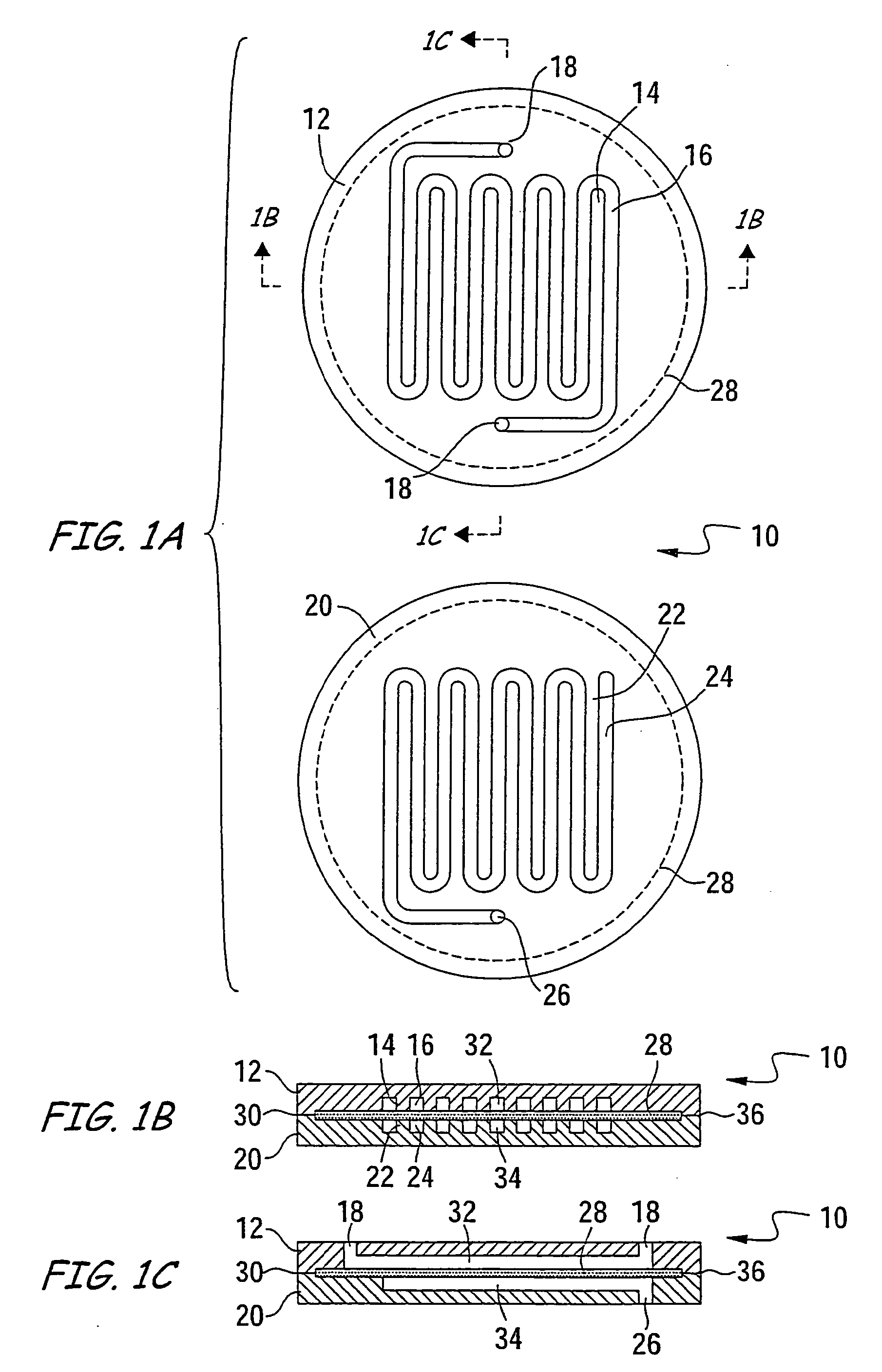
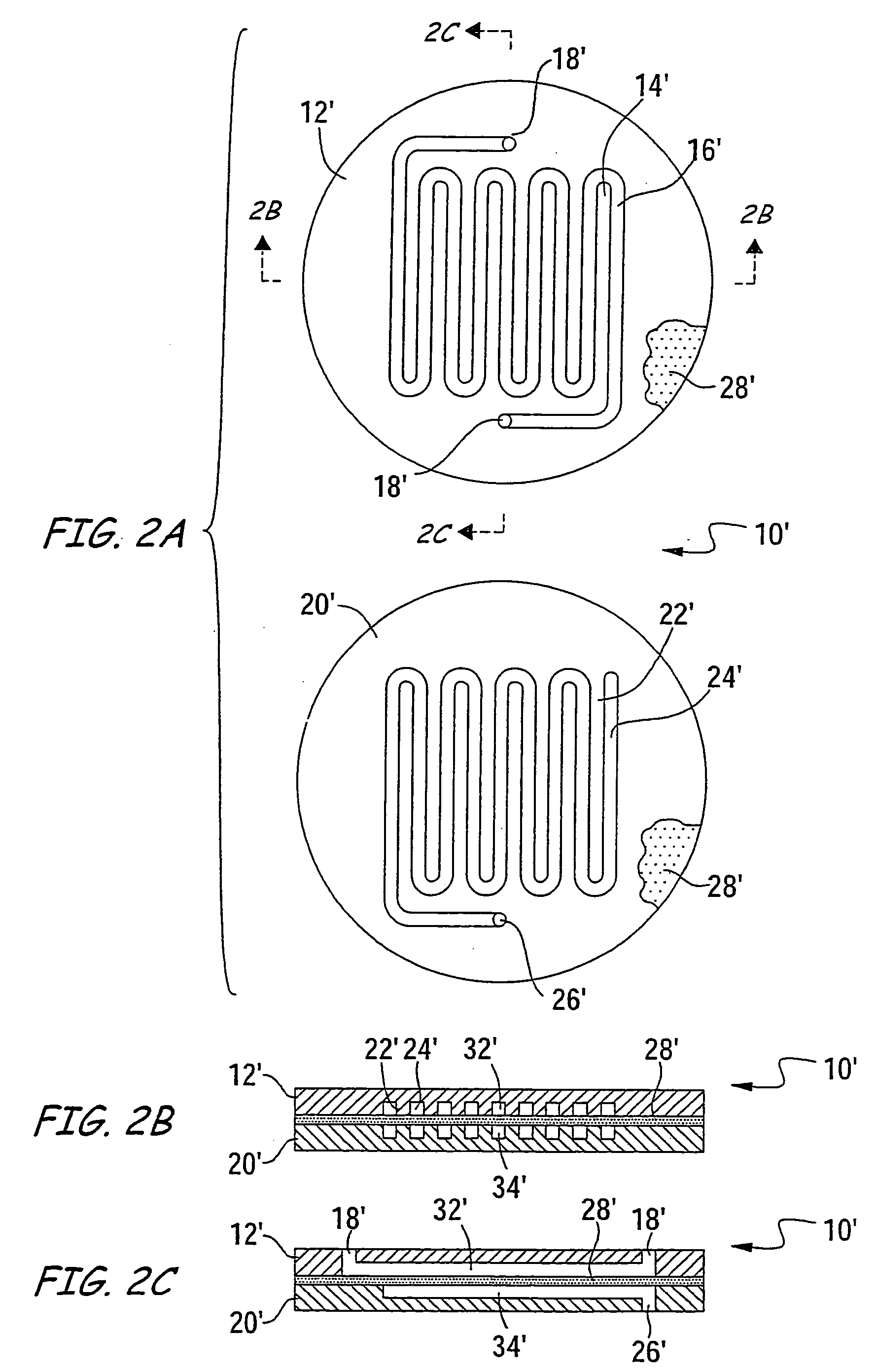
[0026] The disclosed porous membrane microstructure device may be applicable for use in separator, extractor, diffuser, and contactor applications. The lack of traditional microlamination process steps during its manufacture provides significant cost savings during the manufacturing process. The unitary construction of the disclosed porous membrane microstructure, among other things, provides ample mechanical support for the porous membrane and substantially eliminates leakage during chemical processing. The disclosed method of manufacturing the porous membrane microstructure is compatible with low cost production, facilitates parallelization, and results in a device that provides advantageous yields.

[0027] The present invention is broadly directed membrane microstructures and methods of their manufacture. Such a membrane microstructure is particularly well suited for chemical processing applications, and may be configured to facilitate catalytic reactions within the membrane micro...


PUM

PropertyMeasurementUnit
pore diametersaaaaaaaaaa
distanceaaaaaaaaaa

Abstract

A membrane microstructure device is disclosed. The membrane microstructure device includes a first glass, ceramic or glass-ceramic plate defining a first recess, a second glass, ceramic or glass-ceramic plate defining a second recess, and a non-metallic porous membrane sandwiched between the first and second plates. The first plate, second plate and porous membrane are joined together and the porous membrane is arranged to cover the first and second recesses to define a first microchannel between the first plate and the porous membrane and a second microchannel in fluid communication with the first microchannel between the second plate and the porous membrane. A method of manufacturing a membrane microstructure device is also disclosed.

Description

BACKGROUND [0001] 1. Field of the Invention [0002] The present invention relates generally to the field of microstructure devices, and more particularly to a microstructure device incorporating a porous membrane. [0003] While the present invention is subject to a wide range of applications, it is particularly well suited for extractor, separator, diffuser, and contactor applications in the field of microfluidic reactor systems. [0004] 2. Technical Background [0005] Reactor systems incorporating porous membranes, known generally as membrane reactors, have typically been used to achieve separation of multi-phase complex feeds, or to filter a single phase. Generally speaking, the porous membrane within conventional membrane reactors may exhibit micro-to-macro porosity, and may be fabricated from a number of materials. Porous materials are commonly categorized according to their (average) pore size. Microporous materials generally have pore diameters less than or equal to 10 nanometers ...

Claims


Application Information

Patent Timeline
Patent Type & Authority Applications(United States)
IPC IPC(8): B01D61/18B01D63/08B01D67/00B01D71/04B01J19/00
CPCB01D61/18B01D2313/38B01D63/087B01D67/0041B01D71/04B01J19/0093B01J2219/00783B01J2219/00788B01J2219/00831B01J2219/00835B01J2219/00844B01J2219/0086B01D67/0046B01D67/0088B01D2323/18B01D2323/46B01D2325/10B01D63/088B01D2313/025B01D63/081B01D2313/221B01J19/00B01D67/00411
Inventor CAZE, PHILIPPEGUERMEUR, CELINE CLAUDELETOURNEUR, DIDIER H.THEMONT, JEAN-PIERRENSIMBA, JEAN WAKUWOEHL, PIERRE
Owner CORNING INC
Why Eureka
Try Eureka