Receiver circuit having an optical reception device

a technology of optical reception and receiver circuit, which is applied in the direction of amplifiers with semiconductor devices only, amplifier modifications to reduce noise influence, amplifiers with semiconductor devices/discharge tubes, etc., can solve the problem that the optical receiver circuit is always subject to noise, and achieve optimal noise behavior, reduce current noise of the amplifier, and improve the effect of optical sensitivity

Active Publication Date: 2005-08-04
II VI DELAWARE INC
View PDF4 Cites 8 Cited by
  • Summary
  • Abstract
  • Description
  • Claims
  • Application Information

AI Technical Summary

Benefits of technology

[0011] In one development of the invention, the amplifier furthermore has at least one gain control terminal, by means of which the gain of the amplifier can be changed over at least between two gain values at the user end. This enables an optimal optical sensitivity: this is because the adjustability of the gain of the amplifier makes it possible to set the maximum gain of the amplifier depending on the prescribed bandwidth, or bandwidth to be achieved, of the receiver circuit. By way of example, on account of the approximately constant bandwidth (B)-gain (V) product (B*V=K; K results from the individual configuration of the receiver circuit), it is possible to set the maximum gain V and thus the maximum sensitivity of the receiver circuit by choosing V=K/B. The receiver circuit can thus be used optimally for different data rates. Thus, on account of the gain that can be changed over, the receiver circuit can be individually adapted for example to transmission rates ...

Problems solved by technology

An optical receiver circ...

Method used


Image

  • Receiver circuit having an optical reception device
  • Receiver circuit having an optical reception device
  • Receiver circuit having an optical reception device

Examples


Embodiment Construction

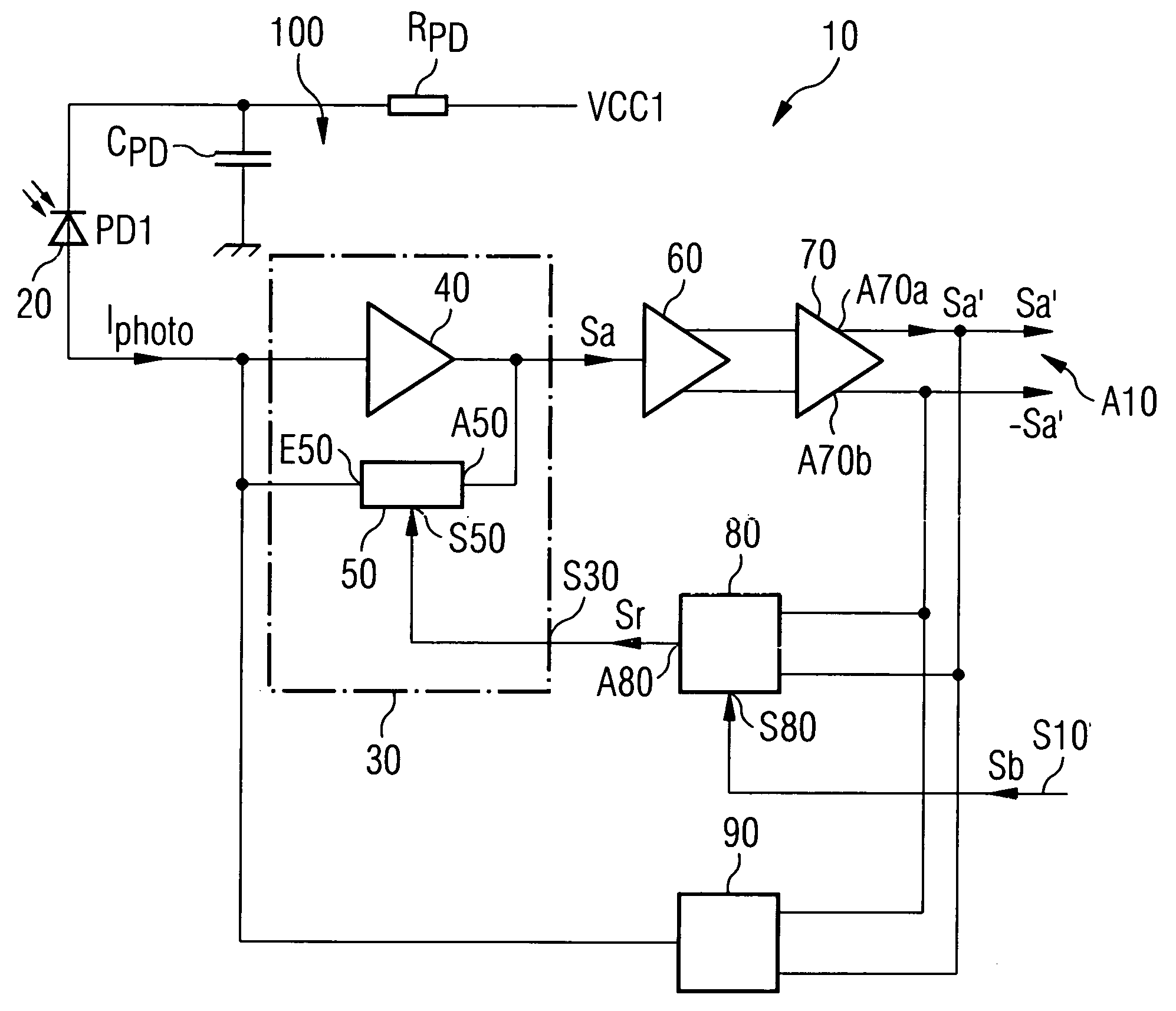
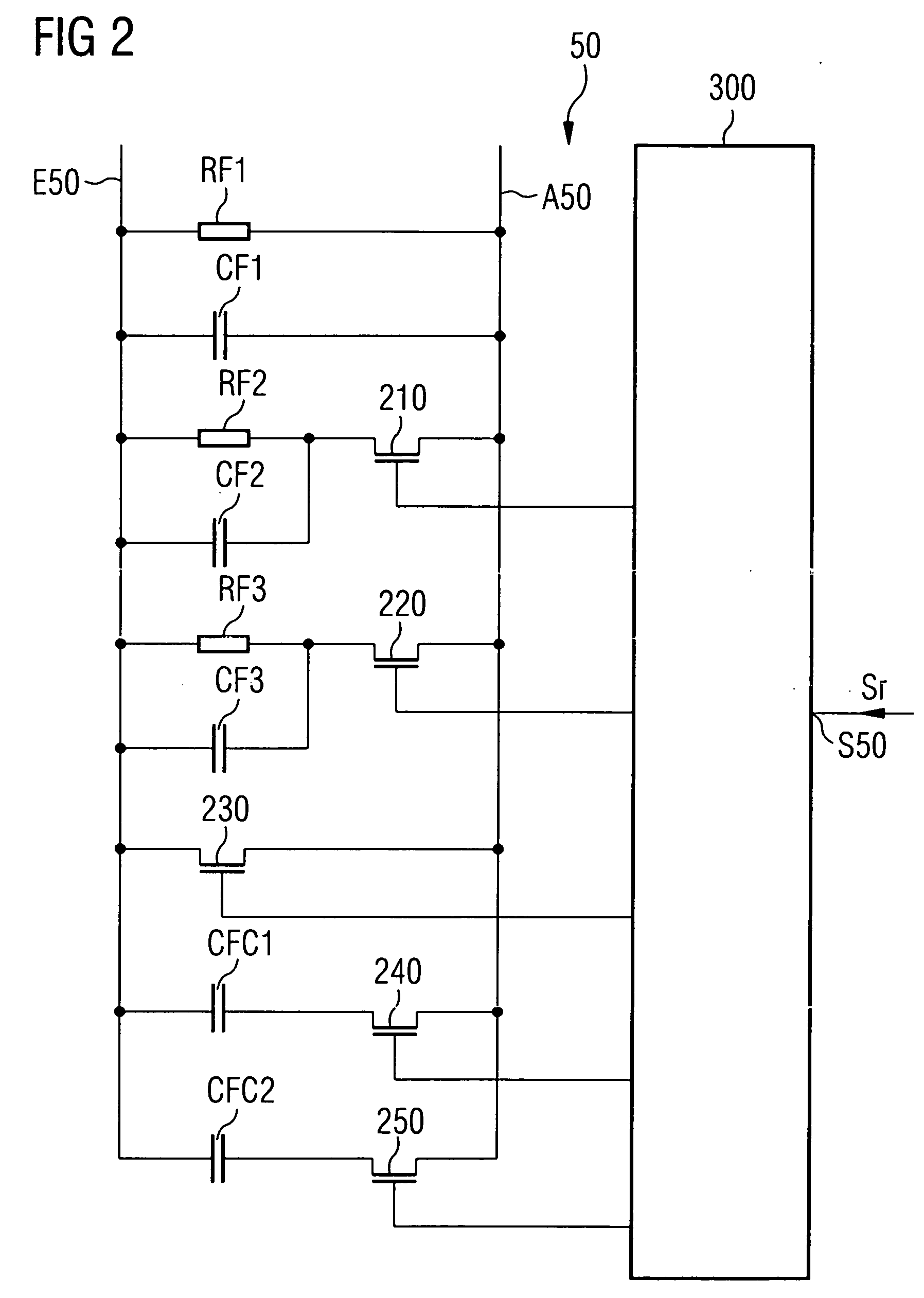
[0022]FIG. 1 reveals a receiver circuit 10 with a photodiode 20 as optical reception device. A transimpedance amplifier 30 is arranged downstream of the photodiode 20. The transimpedance amplifier 30 comprises a voltage amplifier 40, for example an operational amplifier, and a feedback impedance 50. The feedback impedance 50 is connected to the input end of the operational amplifier 40 by its terminal E50 and to the output end of the operational amplifier 40 by its terminal A50.

[0023] At the output end, the transimpedance amplifier 30 is additionally connected to a differential amplifier 60, which amplifies the output signal Sa of the transimpedance amplifier 30. A further amplification of the signal is effected by a second differential amplifier 70 arranged downstream of the first differential amplifier 60.

[0024]FIG. 1 furthermore reveals a control circuit 80, which, at the input end, is connected to the two outputs A70a and A70b of the second differential amplifier 70. The contr...


PUM


Abstract

A receiver circuit having an optical reception device and having an amplifier connected to the reception device, the amplifier also having a circuit for setting the operating point of the amplifier and also at least one control terminal of the circuit, by which the operating point of the amplifier can be selectively changed between at least two values at the user end. The receiver circuit according to the invention enables a noise optimization of the amplifier by virtue of an adjustability of the operating point of the amplifier.

Description

RELATED APPLICATION [0001] The present application claims priority of U.S. Patent Application Ser. No. 60 / 540,870 filed by Karl Schrodinger on Jan. 30, 2004.FIELD OF THE INVENTION [0002] The invention relates to a receiver circuit having an optical reception device and having an amplifier connected downstream of the optical reception device. In particular, the invention relates to a receiver circuit having a transimpedance amplifier for optical transmission systems. BACKGROUND OF THE INVENTION [0003] Receiver circuit having an optical reception device are known in which light incident on the optical reception device—for example, light from an optical waveguide of an optical data transmission system—is detected by the optical reception device with formation of an electrical signal (e.g. a photocurrent) and the electrical signal is subsequently amplified by the amplifier connected downstream. [0004] An optical receiver circuit having an optical reception device and having an amplifier...

Claims


Application Information

Patent Timeline
IPC IPC(8): H03F1/26H03F1/30H03F3/08
CPCH03F1/26H03F3/087H03F1/30
Inventor SCHRODINGER, KARL
Owner II VI DELAWARE INC
Why Eureka
Try Eureka