Methods and apparatus for implementation of an antenna for a wireless communication device

a wireless communication device and antenna technology, applied in the direction of antenna earthing, resonance antenna, radiating element structure, etc., can solve the problems of increasing interest and concern, sar represents a perceived risk of long-term exposure of head tissues, and the length of microstrips has become a limitation, so as to reduce sar

Inactive Publication Date: 2005-08-04
SOUTHERN METHODIST UNIVERSITY
View PDF16 Cites 30 Cited by
  • Summary
  • Abstract
  • Description
  • Claims
  • Application Information

AI Technical Summary

Benefits of technology

[0029] In accordance with one or more further aspects of the present invention, a method includes applying a lossy magnetic medium over all or portions of the second side of the ground plane and over all or portions of the second microstrip line so as to provide a mechanism to absorb radiated near fields that are a result of RF current that flows from the first side of the ground plane over an edge onto the second side of the ground plane, thereby reducing SAR.

Problems solved by technology

Microstrip length has become a limitation as cellular telephones continue to shrink.
SAR represents a perceived risk for long term exposure of head tissues as a consequence of the deep penetration of RF radiation in tissues of biological origin at frequencies used for cellular communication.
SAR is already a characteristic that is limited for cellular devices sold in certain countries such as Japan and Korea, and SAR may also become limited in devices sold in the U.S. As general uses for compact and portable transmitters become widespread, personally absorbed radiation will become an issue of greater interest and concern.
Design directions that can be taken to limit SAR are reduction in transmitted power, which is undesirable because it limits the useful range of the telephone or other transmitting device, locating the antenna farther from a person's head or other body part so as to reduce personal exposure to RF energy, which raises marketability issues for cellular telephone and other portable or compact products, increasing antenna efficiency so that less power is required to operate the telephone or other communication device, which is presently a design challenge for small antennas, and possibly altering the configuration of the antenna and its adjacent structures to reduce strength of the near-field radiation adjacent the user's head or other body part without adversely affecting the antenna radiation pattern or other antenna attributes such as antenna gain, size, or input impedance.
In many practical applications, as in cellular telephones, such limited size reduction may not be sufficient.

Method used


Image

  • Methods and apparatus for implementation of an antenna for a wireless communication device
  • Methods and apparatus for implementation of an antenna for a wireless communication device
  • Methods and apparatus for implementation of an antenna for a wireless communication device

Examples


Embodiment Construction

[0044] The making and using of the presently preferred embodiments are discussed in detail below. It should be appreciated, however, that the present invention provides many applicable inventive concepts that can be embodied in a wide variety of specific contexts. The specific embodiments discussed are merely illustrative of specific ways to make and use the invention, and do not limit the scope of the invention.

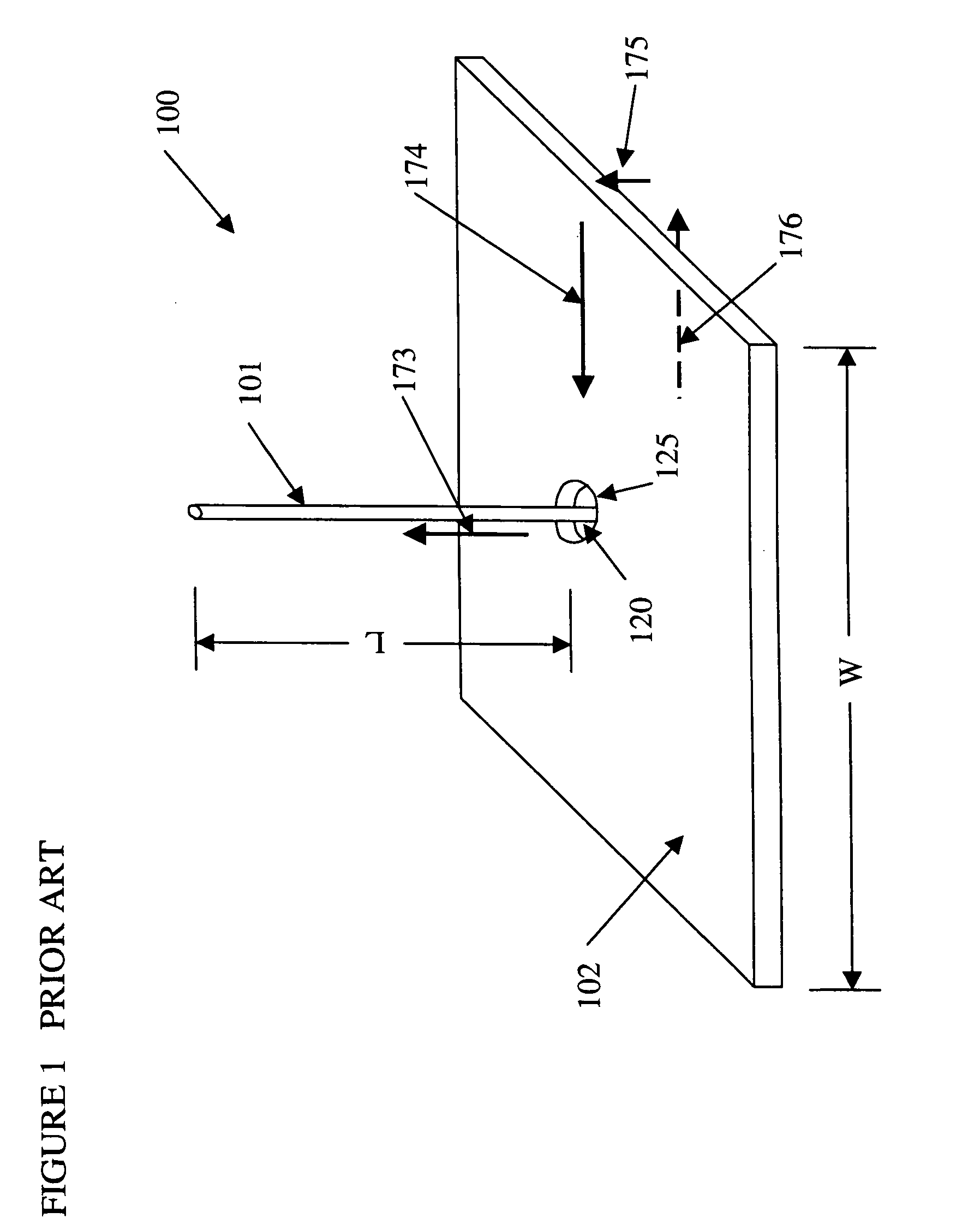
[0045] Reference is now made to the drawings, wherein like designations indicate like elements, as well as numerals ending in the same last two digits. Referring initially to FIG. 1, a monopole antenna 100 of the prior art is illustrated. The monopole antenna 100 includes a conductive wire 101 extending above a ground plane 102. The monopole antenna is fed through an aperture 125 in the ground plane from a feed point 120 by an RF power source (not shown). The monopole antenna extends a distance L above the ground plane, typically about a quarter wavelength at the transmitti...


PUM


Abstract

A wireless communication device includes an antenna configured with two conductive elements separated by an insulating medium providing a separation distance. One conductive element is a ground plane and the other is a microstrip line. The microstrip line and the ground plane exhibit a characteristic impedance that may vary along the length of the microstrip line. The separation distance of the microstrip line from the ground plane is changed to reduce the resonant frequency of the microstrip line. A second microstrip line with an open end and another end shorted to the ground plane is operative to prevent RF current from flowing on the backside of the ground plane. A backside of the ground plane and the second microstrip line may be covered with a lossy magnetic medium to reduce the near field in the space above the backside of the ground plane.

Description

TECHNICAL FIELD [0001] The present invention relates to methods and apparatus for providing a microstrip antenna of compact size such as may be used in wireless communication devices and the like. BACKGROUND [0002] The widespread use of cellular telephones and other compact or portable RF communication devices such as toll-tag readers, identification card readers, and devices for scanning items in inventory has resulted in intense interest in employing antennas with high efficiency and compact size. The early implementations of mobile cellular telephony devices were of lunchbox size or larger, and required a power level that generally required a substantial power source such as provided by an automotive alternator and battery. However, as cellular technology has evolved with paralleling reductions in size and power requirements, cellular telephones and other portable communication devices have become small enough to fit easily into the palm of one's hand, and can be operated for pra...

Claims


Application Information

Patent Timeline
Patent Type & Authority Applications(United States)
IPC IPC(8): H01Q1/22H01Q1/24H01Q1/38H01Q1/48H01Q1/52H01Q9/04H01Q17/00
CPCH01Q1/2216H01Q1/243H01Q1/245H01Q17/001H01Q1/528H01Q9/0414H01Q1/48
Inventor LEE, CHOON SAE
Owner SOUTHERN METHODIST UNIVERSITY
Why Eureka
Try Eureka