

Wireless communication circuit and wireless communication apparatus using the same
a wireless communication and circuit technology, applied in transmission monitoring, sustainable buildings, high-level techniques, etc., can solve the problems of power consumption and faster consumption of the battery mounted in the main body of the information terminal device, and achieve the effect of reducing power consumption and low power consumption
- Summary
- Abstract
- Description
- Claims
- Application Information
AI Technical Summary
Benefits of technology
Problems solved by technology
Method used
Image

Examples
embodiment 1
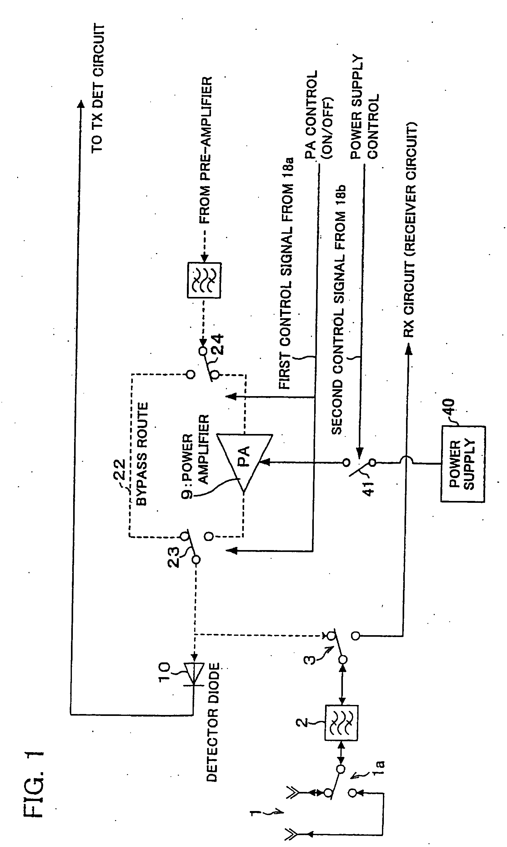
[0061]FIG. 1 is a block diagram showing a high frequency circuit section in a wireless communication apparatus of an embodiment 1 according to the present invention; and a main part of the high frequency circuit section includes a power amplifier 9, a bypass route 22, and route switches 23 and 24 for a transmission signal.
[0062] The wireless communication apparatus of the present invention, which is a wireless communication apparatus for use in an information terminal device, includes an antenna 1; the power amplifier 9 for transmission, which is to be connected to the antenna 1 when it is selected; the bypass route 22 for bypassing a signal route (amplification route) of the power amplifier 9; and the route switches 23 and 24 (first switches) for selectively switching over between the signal route of the power amplifier 9 and the bypass route 22.
[0063] The transmitter circuit section in the high frequency circuit has a detector diode 10. The detector diode 10, which is a schottky...
embodiment 2
[0080]FIG. 3 is a block diagram showing a high frequency circuit section in a wireless communication apparatus of another embodiment according to the present invention. The high frequency circuit section in FIG. 3 is modified from that of FIG. 1 as follows. A main part of the high frequency circuit section includes a power amplifier 9 for transmission, and a fixed attenuator 22a provided instead of the bypass route 22 shown in FIG. 1, and route switches 23 and 24 for switching over routes for a transmission signal. A detection diode 10 has the same function as that of the embodiment 1.
[0081] Next described is an operation process of this configuration. This card-type wireless communication apparatus performs two-level switching-over by using an RSSI value in accordance with a distance from a host machine (e.g. an apparatus such an access point, a router or the like; or a transmitting box or the like). Operation of a controller 18 for this case is explained blew, referring to the fl...
embodiment 3
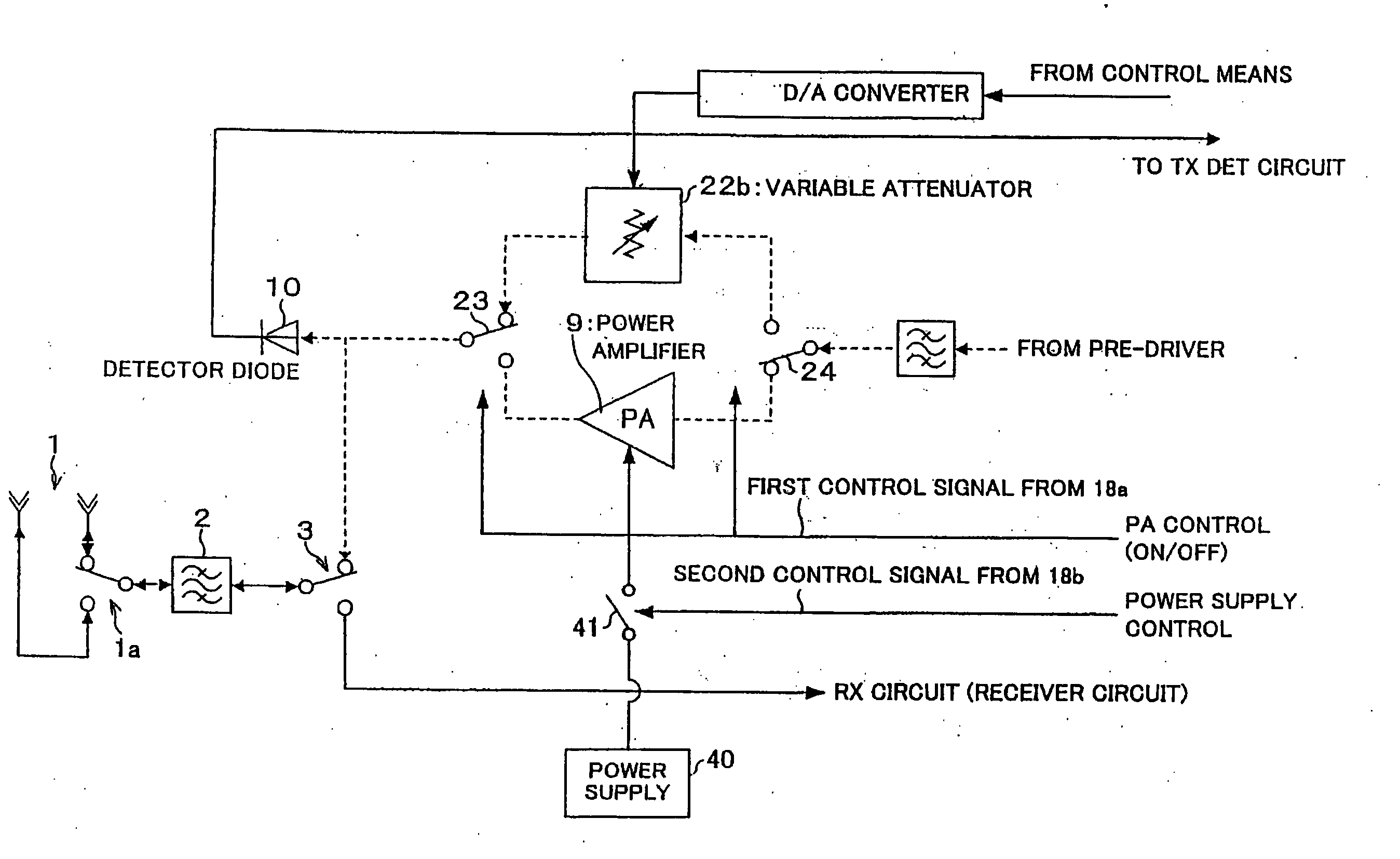
[0093]FIG. 4 is a block diagram showing a high frequency circuit section in a wireless communication apparatus of yet another embodiment according to the present invention. The high frequency circuit section in FIG. 4 is modified from the arrangement of FIG. 1 as follows. A main part of the high frequency circuit section includes a power amplifier 9 for transmission, and a variable attenuator 22b provided instead of the bypass route 22 shown in FIG. 1, and switches 23 and 24 for switching over routes for a transmission signal. A role of a detection diode 10 is the same as the previous description.
[0094] Next described is an operation process of this configuration. By using an RSSI value, the card-type wireless communication apparatus performs such switching-over that attenuation amount can be delicately adjusted according to a distance from a host machine (e.g. an apparatus such an access point, a router or the like; or a transmitting box or the like). Operation of a controller 18 ...
PUM
 Abstract
Description
Claims
Application Information