Proportional solenoid control valve

a solenoid control valve and proportional technology, applied in the direction of fluid pressure control, process and machine control, instruments, etc., can solve the problem of generating unstable control elements, and achieve the effect of reducing the magnetic hysteresis

Inactive Publication Date: 2005-08-11
KOFUROTSUKU
View PDF8 Cites 15 Cited by
  • Summary
  • Abstract
  • Description
  • Claims
  • Application Information

AI Technical Summary

Benefits of technology

[0025] The change in flow rate due to vibration generated from supporting point friction is eliminated by employing the flat square spring applied low friction Teflon coating on one supporting point side face thereof or by employing the circular flat spring having a distance

Problems solved by technology

In such proportional solenoid control valve, if magnetic force is weaker, unstable element for controllin

Method used


Image

  • Proportional solenoid control valve
  • Proportional solenoid control valve
  • Proportional solenoid control valve

Examples


Embodiment Construction

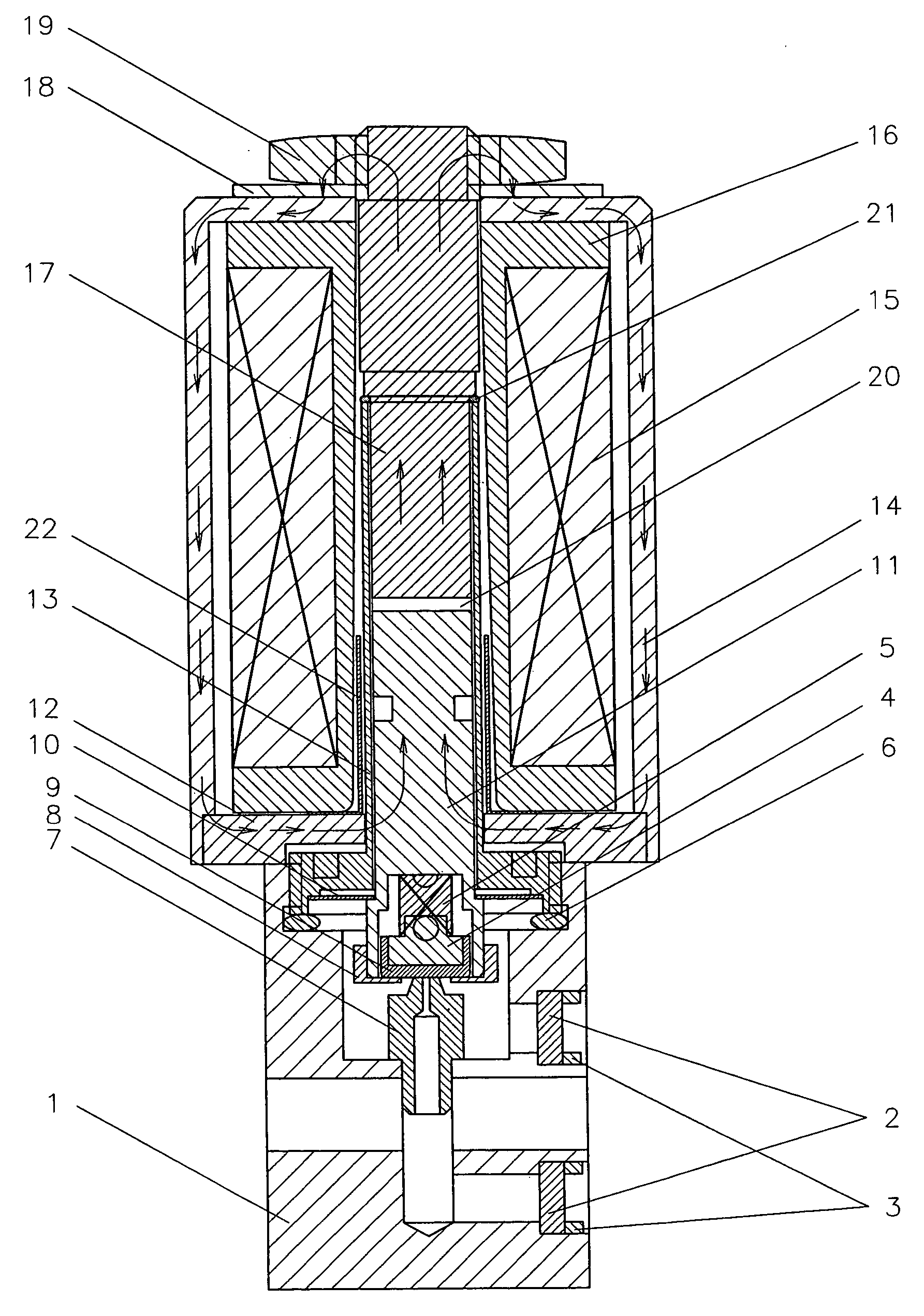
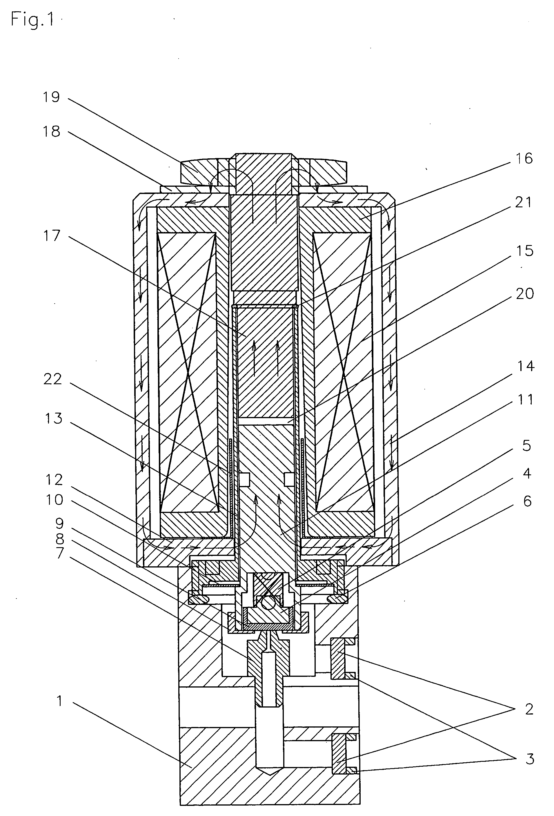
[0032] Referring to FIG. 1, a vertical cross sectional view of a proportional solenoid control valve of an embodiment according to the present invention is illustrated.

[0033] In the proportional solenoid control valve, a magnetic wiring (magnetic coil) 15 is applied to a hollow wiring bobbin 16, and a plunger housing 13, a magnetic rod 17 and a plunger 11, the wiring bobbin 16, and a magnetic assistance sleeve 22 are located coaxially.

[0034] A magnetic yoke 14 has a cylindrical shape. The magnetic rod 17, the plunger housing 13, the wiring bobbin 16, and the magnetic assistance sleeve 22 are located coaxially within the interior of the yoke 14.

[0035] A circular magnetic nut 19 is used to screwing-lock the magnetic rod 17 by interposing a magnetic washer A18 so as to be fixed to the plunger housing 13 by interposing the magnetic coil 15, wiring bobbin 16, the circular shaped magnetic yoke 14, and a magnetic washer B12.

[0036] The plunger housing 13 has a cylindrical shape, and is ...


PUM


Abstract

A proportional solenoid control valve comprises a flat square spring which is wide in maintaining width with respect to displacement of a spring having a greater spring constant, so that accurate control of fluid is realized. The flat square spring has four tubs and is supported with respect to a step face with outer peripheral section thereof. The valve further comprises a sealing mechanism loaded with rubber resilience compensates instability of armature construction and resilient sealing section. The spring constant of the flat square spring is improved by strengthening the magnetic force, thus hysteresis can be made to be smaller.

Description

FIELD OF THE INVENTION [0001] The present invention relates to a proportional solenoid control valve. More particularly, the present invention relates to a proportional solenoid control valve for controlling flow rate of fluid with accuracy. BACKGROUND OF THE INVENTION [0002] A proportional solenoid control valve is generally disclosed in U.S. Pat. No. 5,232,196. U.S. Pat. No. 5,232,196 generally discloses an improved arrangement for a proportional solenoid valve for controlling a flow rate with accuracy. [0003] In such proportional solenoid control valve, if magnetic force is weaker, unstable element for controlling is generated such as frictional thread engagement, affection due to inlet pressure and outlet pressure. [0004] In a proportional solenoid valve a displacement is determined based upon power balancing of a attracting magnetic force and a repulsion force, the attracting magnetic force being a force for attracting a magnetic rod and a plunger to one another by a magnetic f...

Claims


Application Information

Patent Timeline
IPC IPC(8): F16K31/06G05D16/20
CPCG05D16/2013F16K31/0655G05D16/2022
Inventor OGAWA, OSAMU
Owner KOFUROTSUKU
Why Eureka
Try Eureka