
Structure for phase change memory and the method of forming same

structure technology, applied in the field of methods, can solve the problems of increasing the overall size, cost, complexity and power consumption the manufacturing process required to form such a small contact structure is very complicated and therefore has a relatively high process cost. , to achieve the effect of reducing the manufacturing cost of a phase change memory cell, simplifying the structure and reducing the operating curren

Active Publication Date: 2005-08-11
MACRONIX INT CO LTD
View PDF4 Cites 23 Cited by
  • Summary
  • Abstract
  • Description
  • Claims
  • Application Information

AI Technical Summary

Benefits of technology

[0024] The present invention reduces the manufacturing cost of phase change memory cells due to the simplified structure. Further, the operating current can be reduced due to the small contact size that can also provide a low power consumption phase change memory cell or other phase change devices.

Problems solved by technology

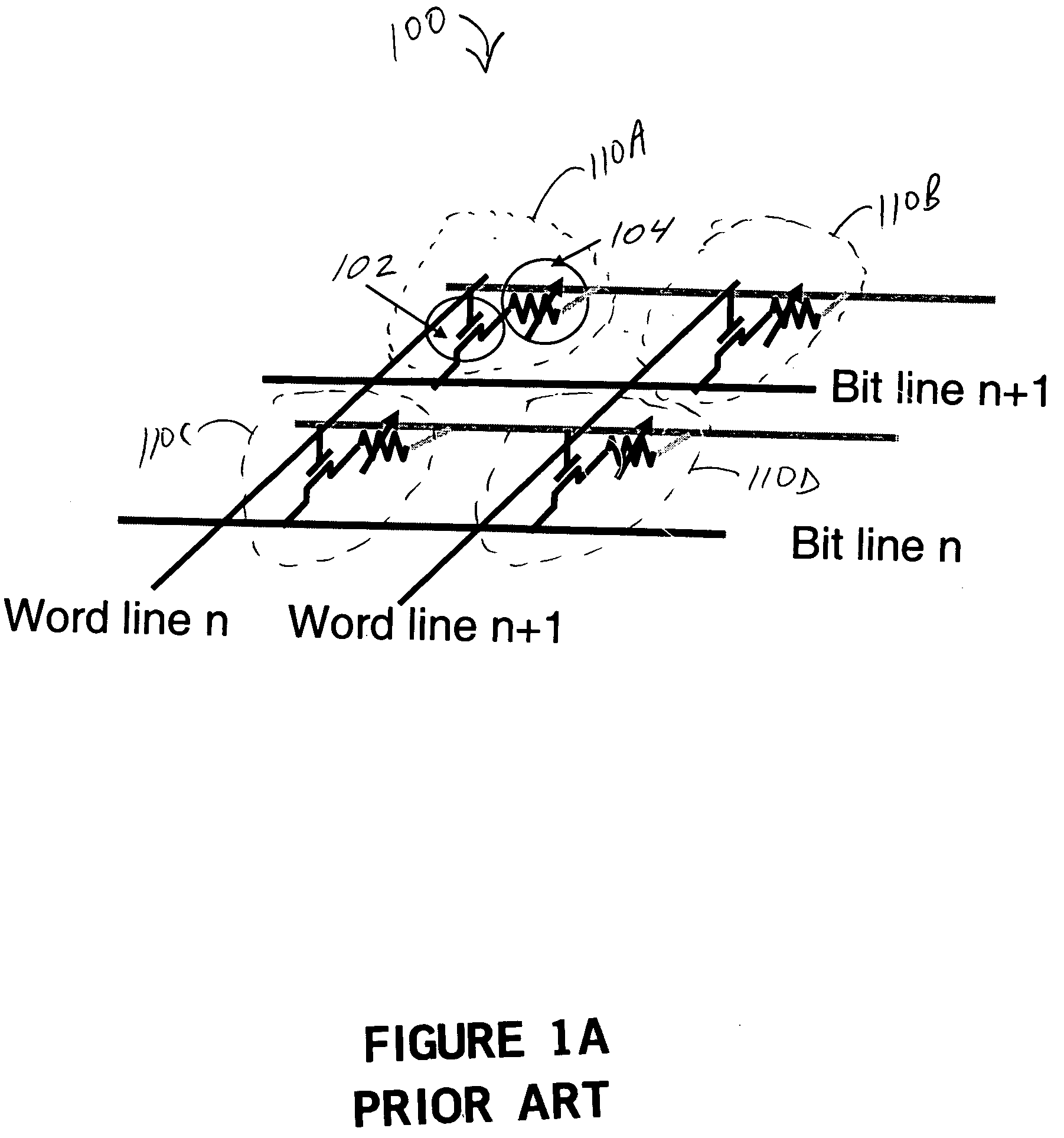
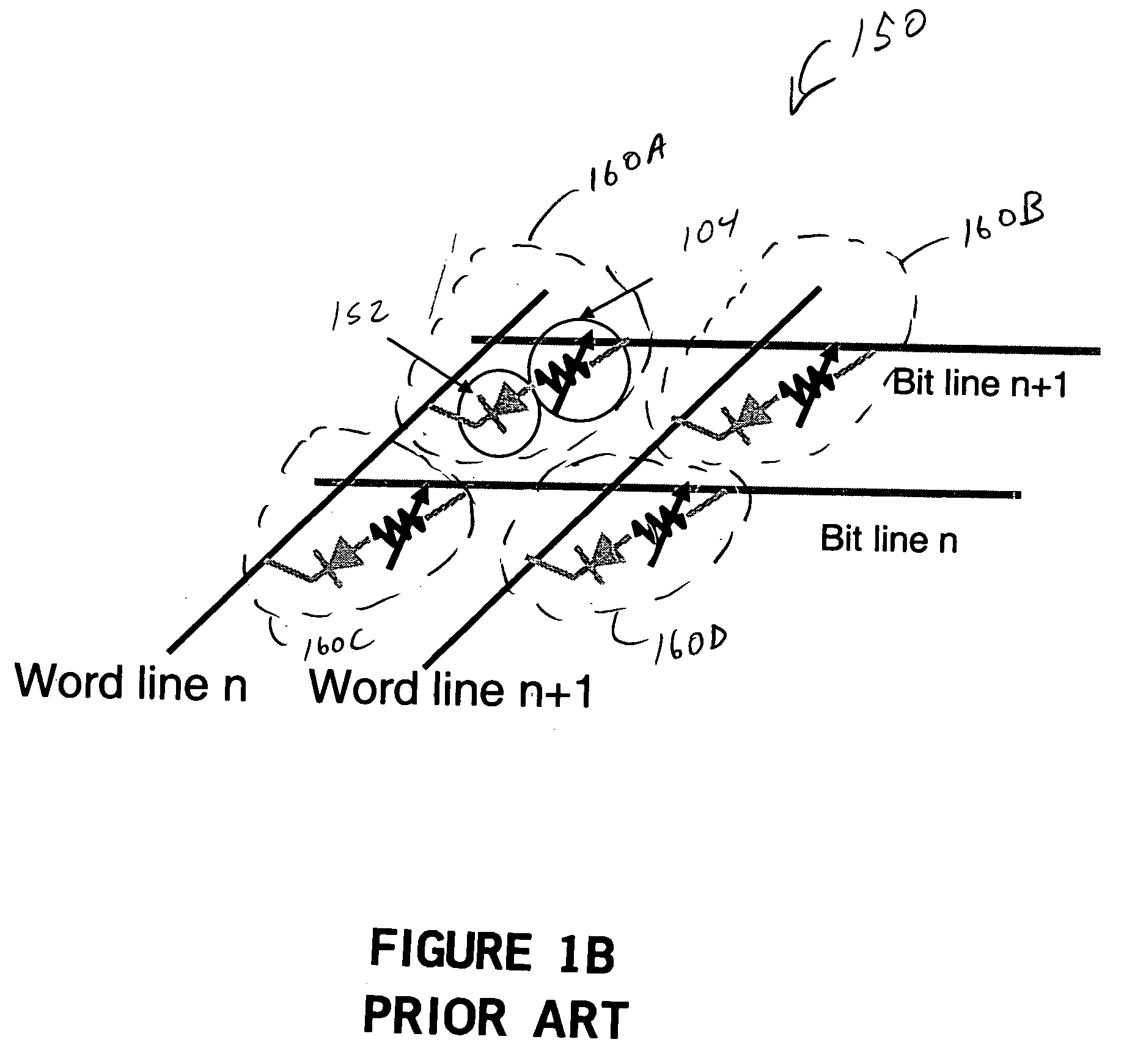
The need of a steering element increases the overall size, cost, complexity and power consumption of a phase change memory cell.
However, the manufacturing processes required to form such a small contact structure is very complicated and therefore has a relatively high process cost.

Method used


Image

  • Structure for phase change memory and the method of forming same
  • Structure for phase change memory and the method of forming same
  • Structure for phase change memory and the method of forming same

Examples


Embodiment Construction

[0036] Several exemplary embodiments for an improved phase change device and phase change memory cell will now be described. It will be apparent to those skilled in the art that the present invention may be practiced without some or all of the specific details set forth herein.

[0037] Phase change memory cells are very fast and nonvolatile. Therefore, phase change memory cells can be an excellent choice for a next generation data storage (i.e., memory). The present invention describes an improved phase change memory cell structure and a method for manufacturing the improved phase change memory cell. The disclosed phase change memory cell is more power efficient than that described in the prior art.

[0038] In one embodiment, the phase change contact size is reduced to a minimum size so as to reduce the drive current while maintaining a sufficient current density. The minimum contact size is limited by the fabrication techniques, and the cost to fabricate the small contact is very hig...


PUM


Abstract

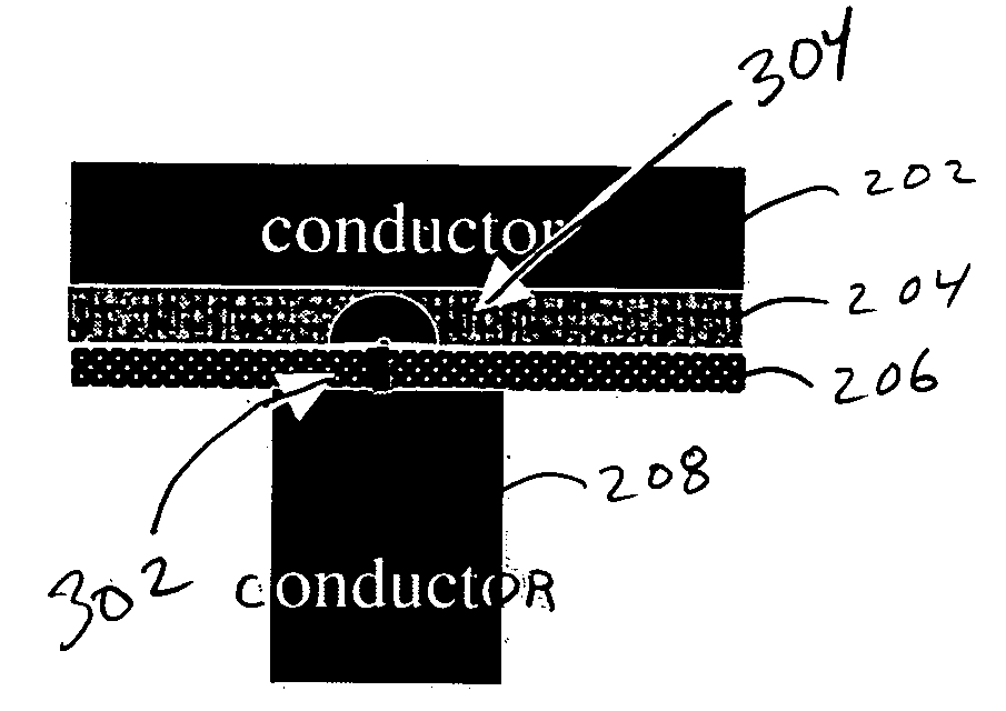
A phase change device includes a first contact electrode structure a phase change material and a first insulating material between the phase change material and the first contact electrode structure and a second contact electrode in contact with the phase change material. A contact structure formed in the first insulating material between the first contact electrode structure and the phase change material is also included. The contact structure is formed by an insulating material breakdown process. A method of forming a phase change device is also described.

Description

CROSS REFERENCE TO RELATED APPLICATIONS [0001] This application claims priority under 35 U.S.C. § 119(e) from U.S. Provisional Patent Application No. 60 / 543,308, filed on Feb. 9, 2004, the disclosure of which is incorporated herein by reference in its entirety.BACKGROUND OF THE INVENTION [0002] 1. Field of the Invention [0003] The present invention relates generally to memory systems, and more particularly, to methods, systems and apparatus for phase change memory cells. [0004] 2. Description of the Related Art [0005] The general concept of utilizing electrically writable and erasable phase change materials (i.e., materials that can be electrically switched between generally amorphous and generally crystalline states) for electronic memory applications is well known in the art. A typical phase change material is a material that has two general states: a generally amorphous state and a generally crystalline state. The phase change material can include one or more chalcogenide compoun...

Claims


Application Information

Patent Timeline
Patent Type & Authority Applications(United States)
IPC IPC(8): H01L27/24H01L29/02H01L45/00
CPCH01L45/12H01L45/141H01L45/1233H01L27/2472H01L45/06H01L45/16H10B63/82H10N70/231H10N70/801H10N70/826H10N70/882H10N70/011
Inventor LEE, MING HSIUCHEN, YI CHOU
Owner MACRONIX INT CO LTD
Learn More