Comparator system and method for comparing an input signal with a reference level using said system

a comparator system and reference level technology, applied in the field of comparator system, can solve problems such as the reliability of the comparator and the accuracy of output data

Active Publication Date: 2005-08-11
SEMICON COMPONENTS IND LLC
View PDF4 Cites 3 Cited by
  • Summary
  • Abstract
  • Description
  • Claims
  • Application Information

AI Technical Summary

Benefits of technology

[0013] The preferred embodiments of the present invention have been developed in view of the above-mentioned and / or other problems in the related art. The preferred embodiments of the present invention can significantly improve upon existing methods and / or apparatuses.
[0014] Among other potential advantages, some embodiments can provide a comparator system high in accuracy and reliability.
[0015] Among other potential advantages, some embodiments can provide a method for comparing an input signal with a reference level with high accuracy and reliability.
[0020] wherein the control circuit selects one of the outputs of the first and second comparators quicker in level change timing, and controls an output signal of the control circuit at the level change timing of the selected output.
[0029] selecting one of outputs of the first and second comparators quicker in level change timing; and

Problems solved by technology

Thus, there is a drawback that the long and uncertain delay time causes a deterioration of the accuracy of the output data and the reliability of the comparator 101.

Method used


Image

  • Comparator system and method for comparing an input signal with a reference level using said system
  • Comparator system and method for comparing an input signal with a reference level using said system
  • Comparator system and method for comparing an input signal with a reference level using said system

Examples


first embodiment

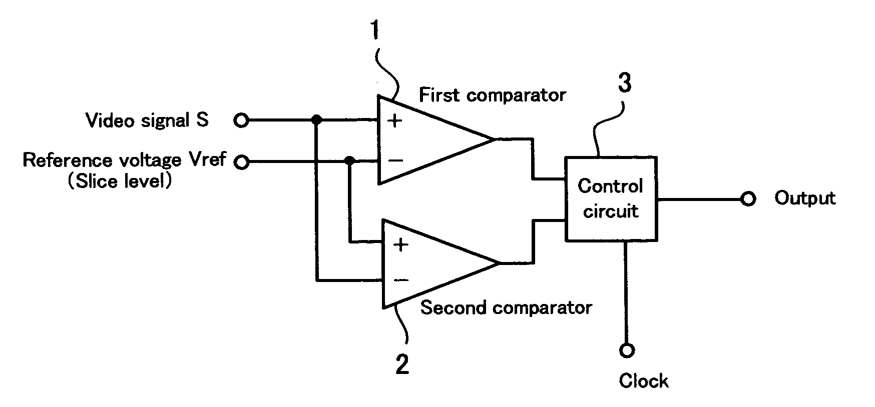
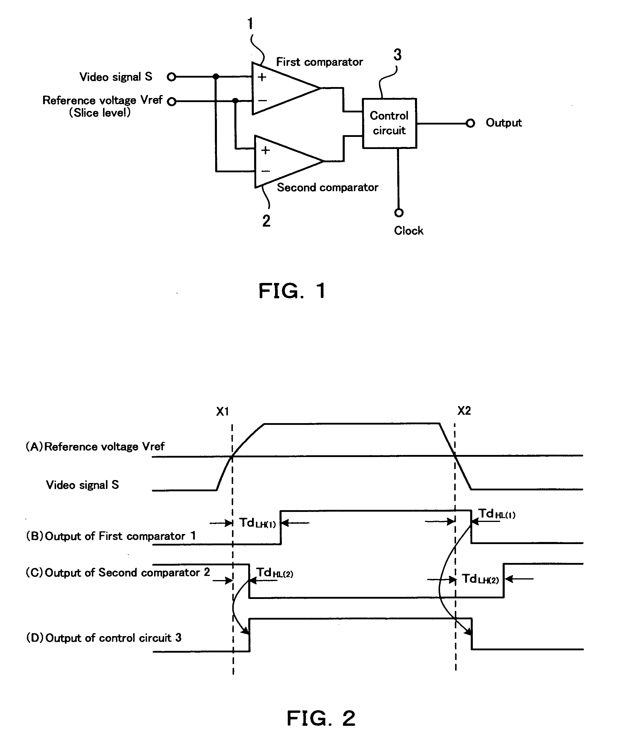
[0043]FIG. 1 shows an example of a block diagram of a comparator system according to the invention. This comparator system includes a first comparator 1, a second comparator 2 and a control circuit 3.

[0044] The first comparator 1 is provided with a non-inverting input terminal, an inverting input terminal and an output terminal. In the first comparator 1, a video signal S is applied to the non-inverting input terminal and a reference voltage Vref as a slice level is applied to the inverting input terminal. This first comparator 1 outputs an H level signal when the level of the video signal S is higher than the level of the reference voltage Vref, and outputs an L level signal when the level of the video signal S is lower than the level of the reference voltage Vref.

[0045] The second comparator 2 is provided with a non-inverting input terminal, an inverting input terminal and an output terminal like the first comparator 1. The non-inverting input terminal of this second comparator 2...

second embodiment

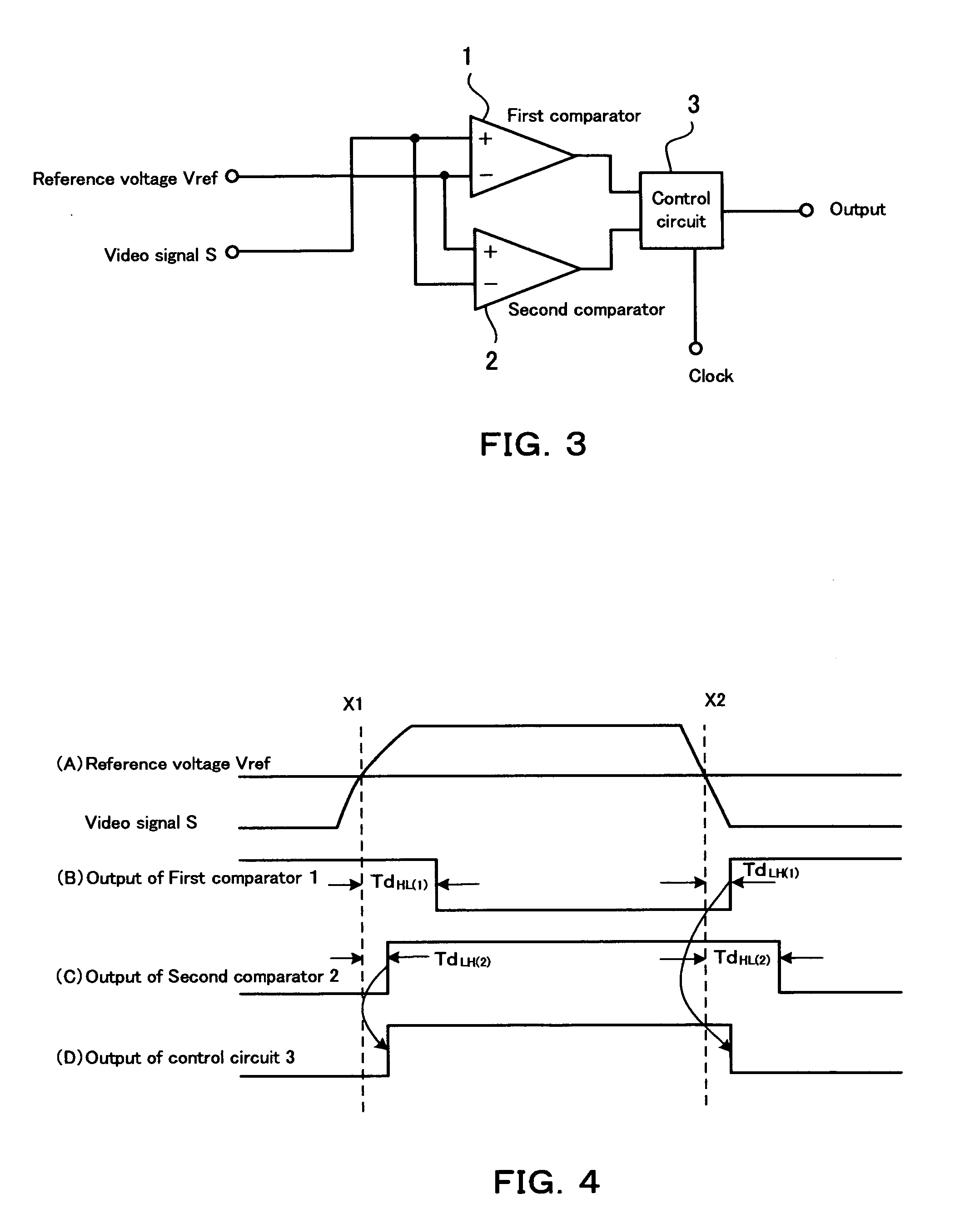
[0060] As will be understood from the above explanation, in this second embodiment too, the output of the control circuit 3 always changes in accordance with the selected output of the first or second comparator 1 or 2 with the shorter time delay.

[0061]FIG. 5 shows an example of the control circuit 3 shown in FIG. 1 and FIG. 3. In FIG. 5 reference numeral “11” denotes a first D-type flip-flop which is configured to input the output of the first comparator 1 and then output a non-inverted output and an inverted output after the normalization with a clock signal. “12” denotes a second D-type flip-flop which is configured to input the output of the second comparator 2 and then output a non-inverted output and an inverted output after the normalization with the dock signal. “13” denotes a third D-type flip-flop which is configured to input an output of a NOR gate 17 and output a non-inverted output after the normalization with the dock signal. The output of this flip-flop 13 becomes an ...


PUM


Abstract

A comparator system for comparing a level of an input signal with a level of a reference signal comprises a first comparator configured to input the input signal to one of input terminals thereof and the reference signal to the other of input terminals thereof, a second comparator configured to input the reference signal to one of input terminals thereof and the input signal to the other of input terminals thereof, and a control circuit configured to input an output of the first comparator and an output of the second comparator. The control circuit selects one of the outputs of the first and second comparators quicker in level change timing, and controls an output signal of the control circuit at the level change timing of the selected output.

Description

[0001] This application claims priority under 35 U.S.C. § 119 to Japanese Patent Application No. P2003-320984 filed on Sep. 12, 2003, the entire disclosure of which is incorporated herein by reference in its entirety. BACKGROUND OF THE INVENTION [0002] 1. Field of the Invention [0003] The present invention relates to a comparator system and a method for comparing an input signal with a reference voltage using the system. More specifically, the present invention relates to a comparator system and a method for comparing an input signal, such as a multiplex data signal for VPS (Video Program System) or PDC (Program Delivery Control), with a reference voltage, which can be preferably used for, for example, retrieving a data signal such as a VPS signal and a PDC signal from a multiplied broadcasting signal during the vertical blanking intervals. [0004] 2. Description of the Background [0005] The following description sets forth the inventor's knowledge and should not be construed as an a...

Claims


Application Information

Patent Timeline
Patent Type & Authority Applications(United States)
IPC IPC(8): H04N5/14H03K5/08H03K5/153H03K5/1532H03K5/1534H04L25/06H04N5/16
CPCH03K5/082G11C7/1084H04L25/061H03K5/1534H04N5/14
Inventor YAMASAKI, SHINICHIOKUBAYASHI, MASANORI
Owner SEMICON COMPONENTS IND LLC
Why Eureka
Try Eureka