Optical display device and projection-type display device

a display device and optical display technology, applied in the direction of instruments, television systems, color signal processing circuits, etc., can solve the problems of inability to accurately transit illumination light having a desired light intensity, inability to avoid the increase in the size of the fist optical modulation element, and inability to adequately demonize the expressive capabilities of cg images. to achieve the effect of high accuracy

Inactive Publication Date: 2005-08-11
SEIKO EPSON CORP
View PDF5 Cites 32 Cited by
  • Summary
  • Abstract
  • Description
  • Claims
  • Application Information

AI Technical Summary

Benefits of technology

[0070] In the case of the constitution, the effect is obtained by which an optical image that has been formed with high accuracy by the afore

Problems solved by technology

However, due to the lack of performance of optical display devices that display that data, there is the problem in which CG images are unable to adequately demons their inherent expressive capabilities.
However, although it is necessary to increase the partition number (resolution) in the second optical modulation elements to reduce display unevenness, since a large number of optical elements are arranged between the second optical modulation element and first optical modulation element, there was the problem of it being difficult to accurately transit illumination light having a desired light intensity distribution to the first optical modulation element.
Consequently, although methods have been considered in which

Method used


Image

  • Optical display device and projection-type display device
  • Optical display device and projection-type display device
  • Optical display device and projection-type display device

Examples


first embodiment

[0100]FIGS. 1 through 16 are drawings showing a first embodiment of an optical display device and projection-type display device of the present invention.

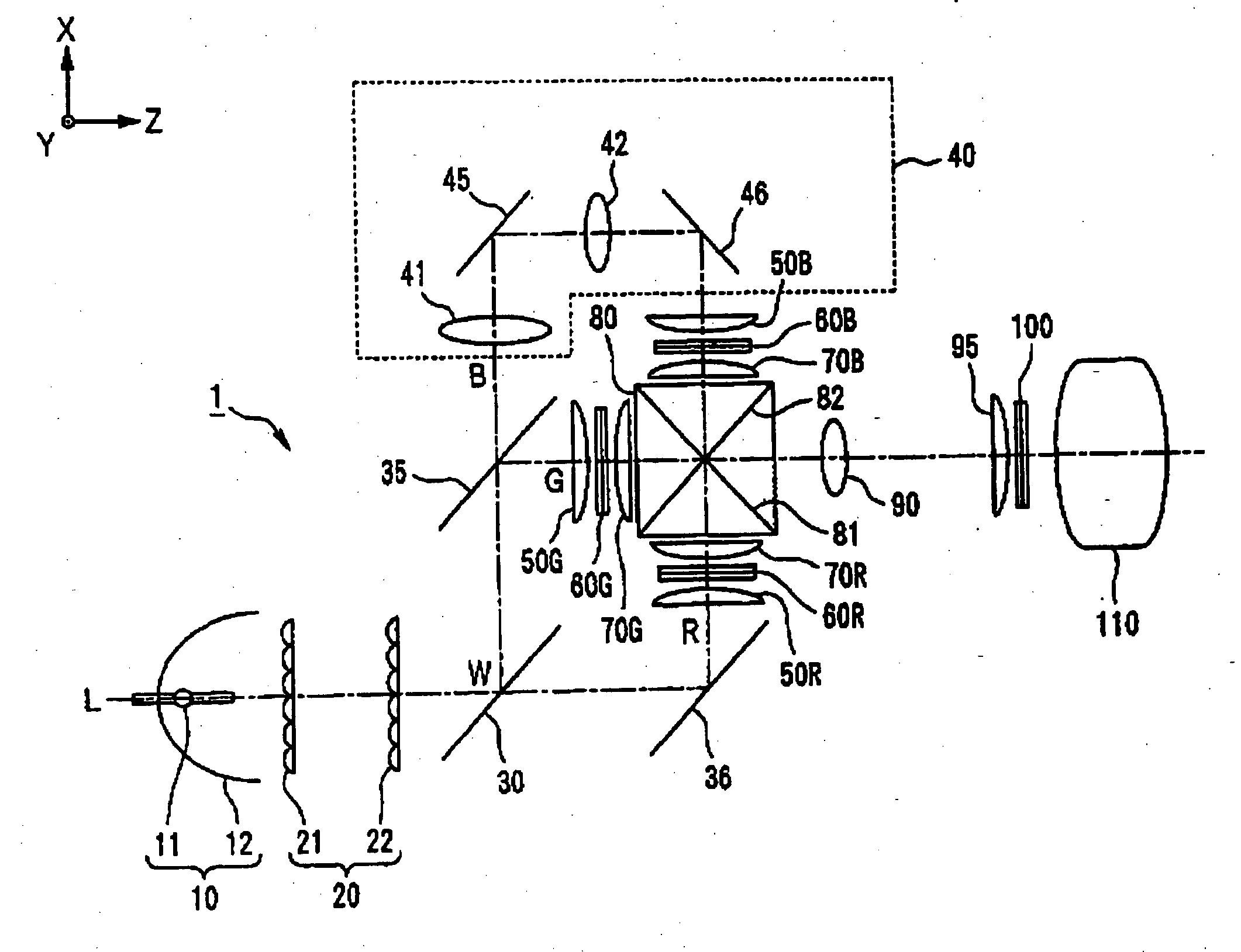
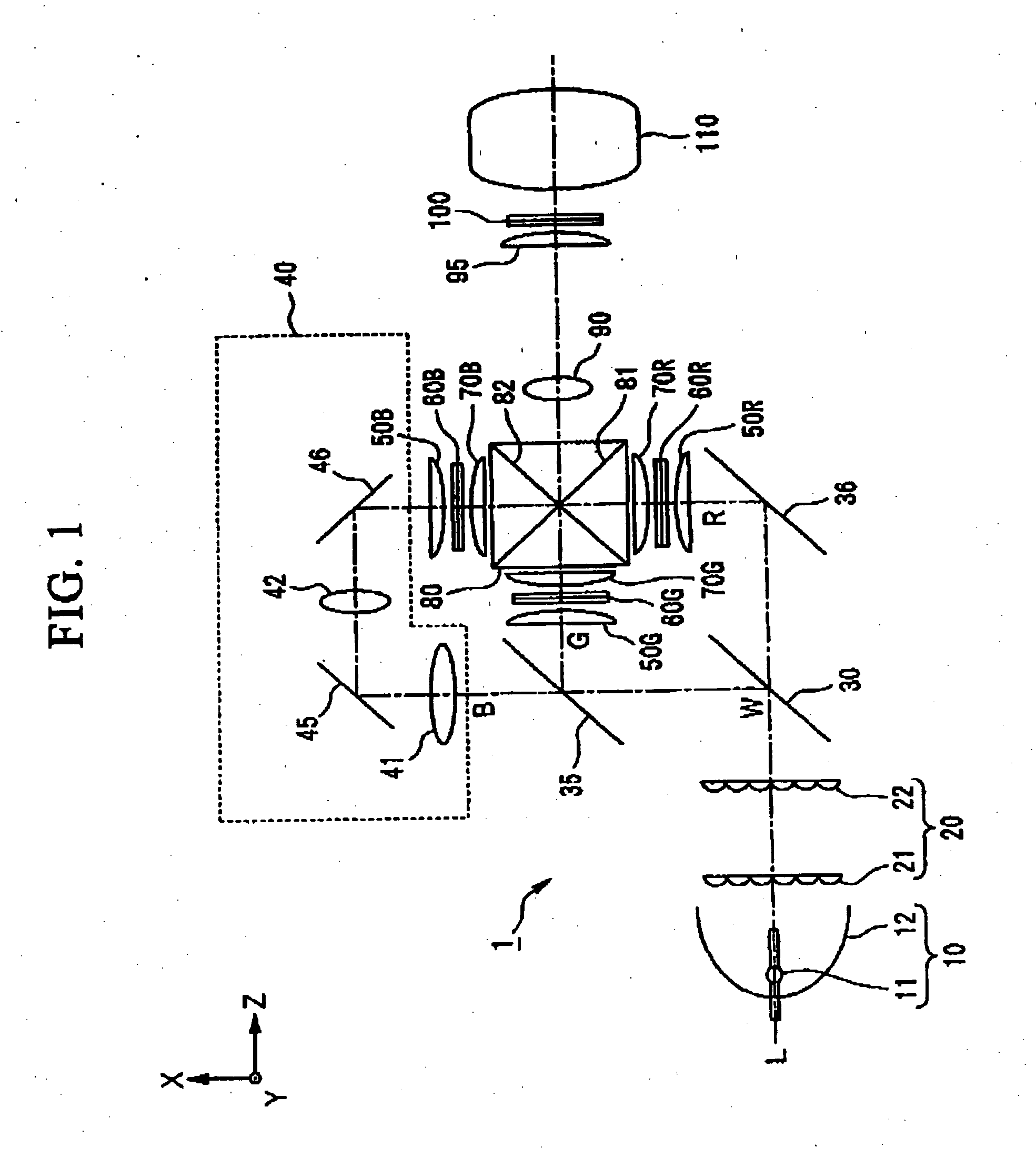
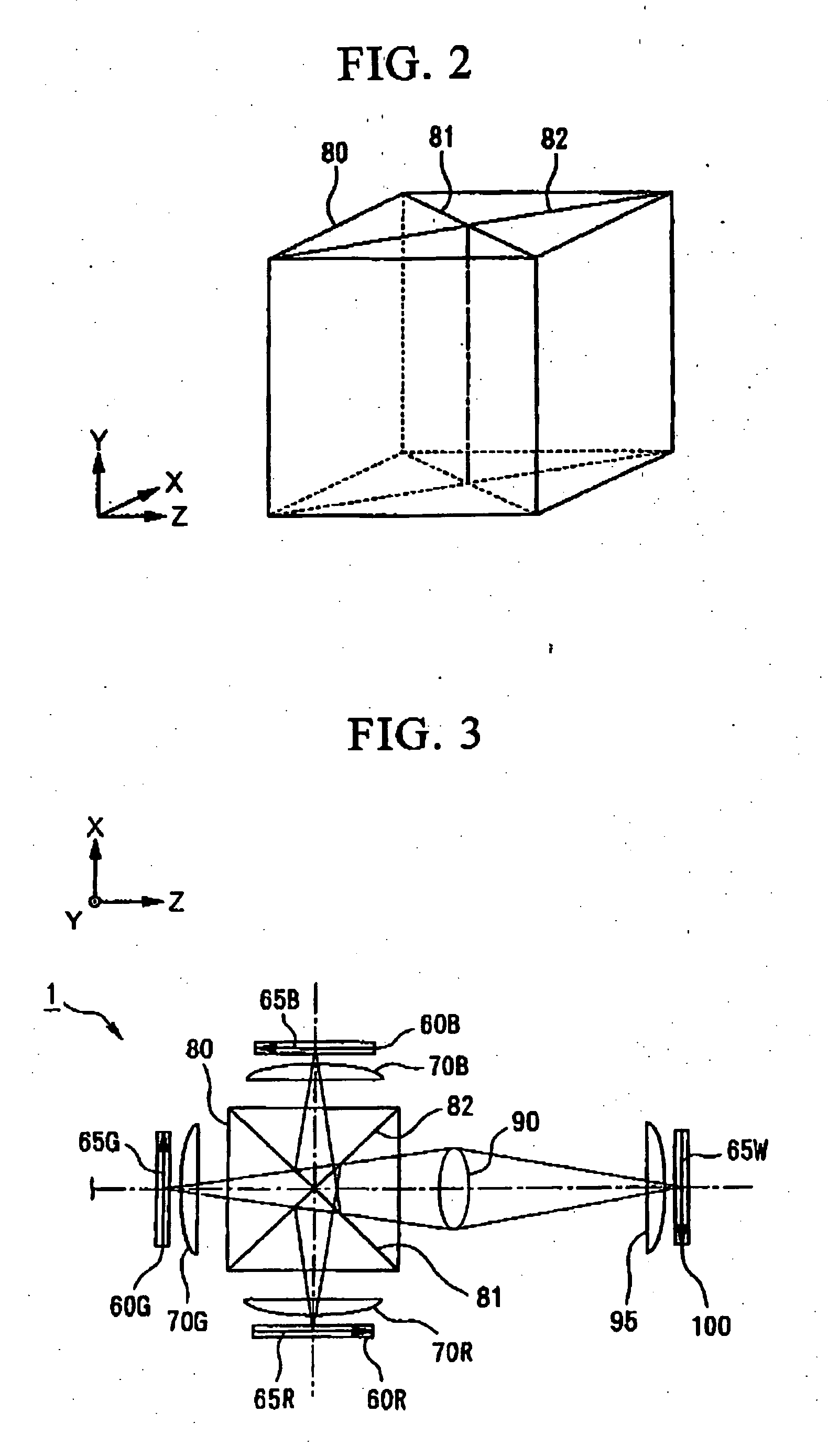
[0101] First, an explanation of the constitution of a projection-type display device 1 of a first embodiment of the present invention is provided based on FIGS. 1 through 3. FIG. 1 is a drawing showing the main optical configuration of projection-type display device 1 of the present invention, FIG. 2 is a drawing showing the constitution of a dichroic prism 80, and FIG. 3 is a drawing showing an example of a relay optical system that transmits an optical image at 1:1 magnification.

[0102] As shown in FIG. 1, projection-type display device 1 includes a light source 10, an optical integrator 20, dichroic mirrors 30 and 35, a reflecting mirror 36, a relay optical system 40, parallelizing lenses 50B, 50G and 50R, liquid crystal light valves 60B, 60G and 60R, incident side lenses 70B, 70G and 70R, a light-synthesizing cross dichroic pr...

second embodiment

Variation of Second Embodiment

[0213] The light-dividing cross dichroic prism and light-synthesizing cross dichroic prism of projection-type display device 130 explained in the second embodiment may also be integrated as in projection-type display device 140 of which the primary optical configuration is shown in FIG. 18. The two dichroic films contained in light-dividing cross dichroic prism 300 and light-synthesizing cross dichroic prism 80 of projection-type display device 130 have the same positional relationship when viewed along the direction of the Y axis. In other words, the blue light reflecting dichroic film in light-dividing cross dichroic prism 300 and the blue light reflecting dichroic film of light-synthesizing cross dichroic prism 80 lie roughly in the same plane, and this applies similarly for the red light reflecting dichroic films. Thus, light-dividing cross dichroic prism 300 and light-synthesizing cross dichroic prism 80 can be integrated in projection-type display...

third embodiment

[0221] The contents of the present invention can also be applied to a so-called direct-view liquid crystal display device (optical display device) in which the final optical image (display screen) formed on the second optical modulation element is viewed directly without enlarging. Namely, as shown in FIG. 22, a liquid crystal display device (optical display device) 160 can be composed by excluding the projection lens 110 in each of the projection-type display devices explained in the aforementioned first and second embodiments. In this type of constitution, since the luminance modulation light valve serves as the image display screen in liquid crystal display device 166, a constitution in which its dimensions are larger and its resolution is higher than the color modulation light valves is preferable.

[0222] In liquid crystal display device 160, although it is necessary to increase the size of emergent side lens 95 to match the in increase size of the color modulation light valves,...


PUM


Abstract

A projection-type display device 1 including a light source 10, an optical integrator 20, dichroic mirrors 30 and 35, a reflecting mirror 36, a relay optical system 40, parallelizing lenses 50B, 50G and 50R, liquid crystal light valves 60B, 60G and 60R, incident side lenses 70B, 70G and 70R, a light-synthesizing cross dichroic prism 80, a relay lens 90, an emergent side lens 95, a liquid crystal light valve 100 and a projection lens 110, and liquid crystal light valve 100 is provided in the rear stage of liquid crystal light valves 60B, 60G and 60R.

Description

BACKGROUND OF THE INVENTION [0001] 1. Field of the Invention [0002] The present invention relates to a device that displays an image by modulating light from a light source through a plurality of optical modulation elements, and more particularly, to a optical display device and projection-type display device preferable for realizing enlargement of luminance dynamic range and number of gradations. [0003] The present application claims priority on Japanese Patent Application No 2003-427208 filed on Dec. 24, 2003, Japanese Patent Application No. 2004-4025409 filed on Feb. 2, 2004, and Japanese Patent Application No. 2004-299285 filed on Oct. 13, 2004, the contents of which are incorporated herein by reference. [0004] 2. Description of the Related Art [0005] Dramatic improvements have been made in recent years in the image quality of liquid crystal displays (LCD), EL, plasma displays, cathode ray tubes (CRT), projectors and other optical display devices, and performance with respect to...

Claims


Application Information

Patent Timeline
IPC IPC(8): G02F1/13G02B13/00G02B13/16G02B27/18G03B21/00G03B21/14H04N5/74H04N9/31
CPCG02B13/0095G02B13/16H04N9/3197H04N9/3105H04N9/3126G03B21/14G03B21/006G03B21/2066G03B33/12G02B27/18
Inventor ITOH, YOSHITAKAYOSHIDA, SHOHEIUCHIYAMA, SHOICHINAKAMURA, JUNICHINITTA, TAKASHIASAHI, TSUNEMORI
Owner SEIKO EPSON CORP
Why Eureka
Try Eureka