[0008] The present detachable filter carrier is advantageous in that it obviates the need to disassemble the cooling
system for the X-ray head assembly or
goniometer to service the
cooling fluid filter, such as for cleaning or replacement thereof, as required with prior X-ray
goniometer heads where the cooling head or manifold was fastened to the X-ray tube so that accessing filters that may be provided in the cooling head necessitated removal of the tube along with the cooling head from the outer housing therefor. In the present invention, a detachable connection between the filter carrier or holder and X-ray head is provided so that with a relatively easy and straightforward detachment operation, the carrier can be removed from the X-ray head leaving the X-ray head tube and housing therefor substantially intact assembled together. In this manner, after servicing of the filter, the carrier can be easily reattached to the X-ray head without concern for proper alignment and orientation of the tube and housing, and particularly the tube
anode assembly and housing window, as is necessary with the previously described cooling system. The detachable connection is preferably a threaded connection such as between the body of the filter carrier itself and the X-ray head or more particularly a cooling head for being secured thereto. Other detachable connections are also contemplated such as bayonet connections, friction fits, and the like.
[0009] In a preferred form, the present invention provides
coolant flow paths within the walls of the outer housing and includes a
filtration site which is accessible from outside of the outer housing. In one arrangement, the present invention provides filter screens carried on a removable carrier or holder which is installed and removed from outside the outer housing without requiring disassembly of the X-ray tube from the outer housing or other components of the X-ray generating device. Accordingly, the
filtration device can be serviced without disturbing the X-ray tube, and in particular, without requiring the X-ray tube to be removed or its surfaces contacted by
service personnel. In one aspect, a removable fluid directing assembly is provided for being removably mounted to the cooling head adjacent the anode region of the X-ray tube with the cooling head installed on the x-ray head. Accordingly, with the fluid directing assembly removed, a limited
visual inspection of the X-ray tube and specifically the otherwise obstructed anode surface can be performed without disassembly of the outer housing and tube or other components of the X-ray device as previously required. In this manner, the anode assembly can be more easily visually inspected for any potential damage thereto as by overheating by simply removing the fluid directing assembly from the cooling head.
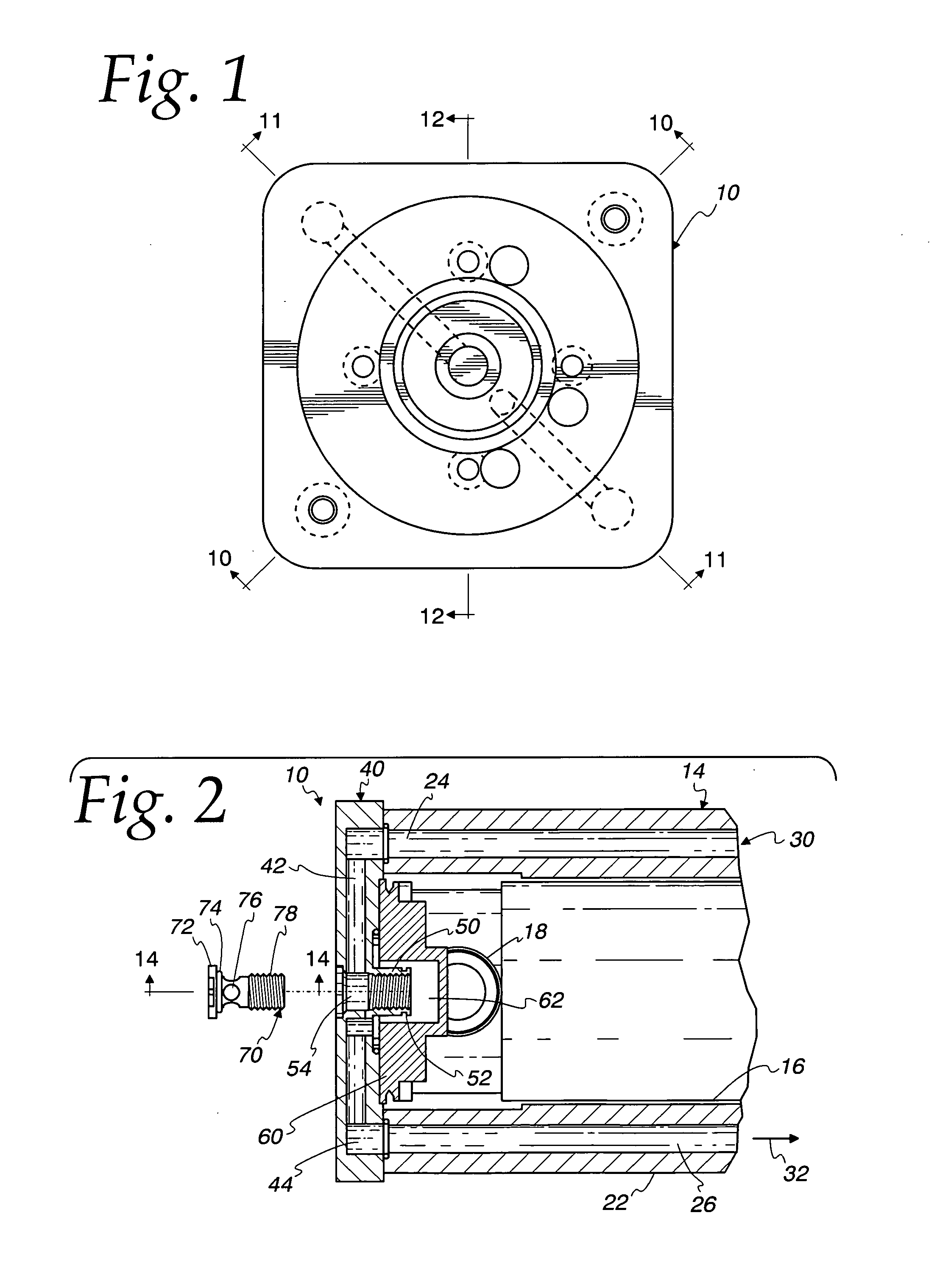
[0010] In one aspect, the present invention provides a cooling system for an X-ray diffraction tube in which a housing in the form of a hollow cylindrical jacket surrounds at least a portion of the X-ray diffraction tube, with the hollow interior of the jacket including a flow channel for channeling flow of a liquid
coolant. The housing further includes a receptacle for receiving a
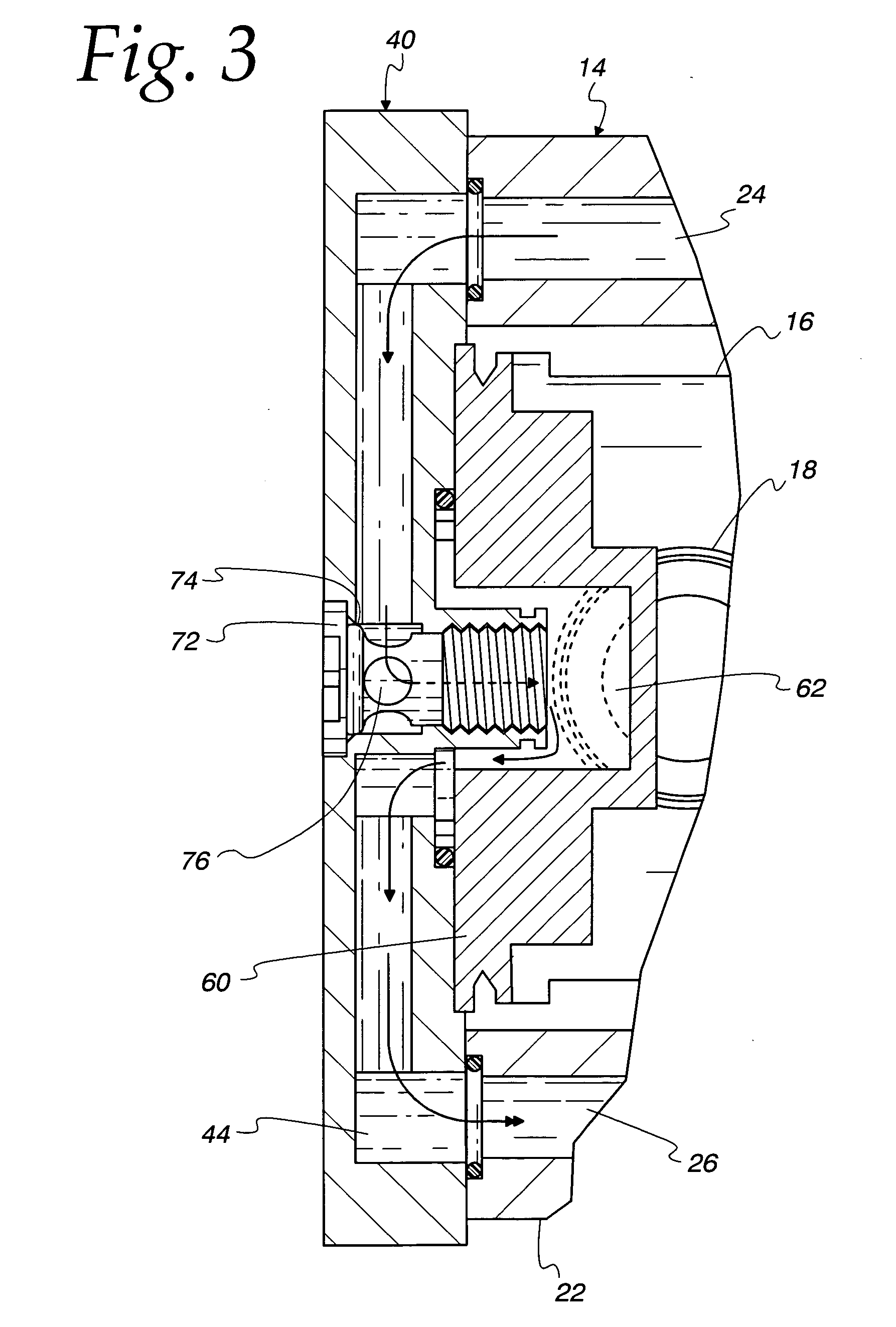
filter holder so as to dispose a filter in the flow channel to thereby provide cleaning of the liquid coolant. In one preferred embodiment, the housing comprises a cylindrical hollow jacket surrounding the X-ray diffraction tube with the hollow interior of the jacket comprising the flow channel. A cooling head engageable with one end of the cylindrical hollow jacket defines an internal flow passageway in communication with the flow channel of the hollow jacket. A receptacle is located in the center of the cooling head with internal passageways within the cooling head extending in radial directions so as to bring flow of coolant into and out of the receptacle. The
filter holder is provided in the form of a bolt or screw
fastener having an enlarged head and a hollow body or stem portion receiving a filter screen. A cross hole extending through the stem provides flow communication with the hollow stem, permitting
coolant flow across the surface of the filter screen. The filter holder is threadingly engaged with the cooling head receptacle portion, thereby allowing the filter holder to be quickly and easily removed from the device, as desired. The filter holder in this embodiment contacts only the cooling head portion of the outer housing and requires neither disassembly of the X-ray head for removing the holder or contact with the X-ray tube. With the filter holder removed from the cooling head, the filter screen can be removed, washed or replaced with a fresh filter screen.
[0011] In other aspects, the present invention can be incorporated in X-ray generating devices in which the space between the X-ray tube and outer housing is filled with a coolant fluid, either gas or liquid.
Coolant flow is conducted through the outer housing to a receptacle portion of the cooling head, as described above. A removable filter holder engaged with the receptacle portion carries a filtration member such as a filter screen to provide continual cleaning of the coolant while
coolant flow conditions are maintained.

