Biometric information verifying apparatus

a biometric information and verification apparatus technology, applied in the field of biometric information verification apparatuses, can solve the problem of difficult reduction of false verification rate, and achieve the effect of reducing the false verification ra

Inactive Publication Date: 2005-08-11
FUJITSU LTD
View PDF8 Cites 50 Cited by
  • Summary
  • Abstract
  • Description
  • Claims
  • Application Information

AI Technical Summary

Benefits of technology

[0017] With the foregoing problems in view, it is an object of the present invention to provide a biometric information verifying apparatus in which a biometric information image is divided into cells and minutia information (for example, the types and the numbers of minutia points, or the presence or absence of minutiae) as well as cell basic information (for example, ridge direction, pitch, and offset amount)...

Problems solved by technology

However, the art is disadvantageous in that it can use only fingerprint shape information in pattern matching (verification), totally ignoring information of fingerprint minutiae (ridge bifurcations and endings).
In this manner, ...

Method used


Image

  • Biometric information verifying apparatus
  • Biometric information verifying apparatus
  • Biometric information verifying apparatus

Examples


sixth embodiment

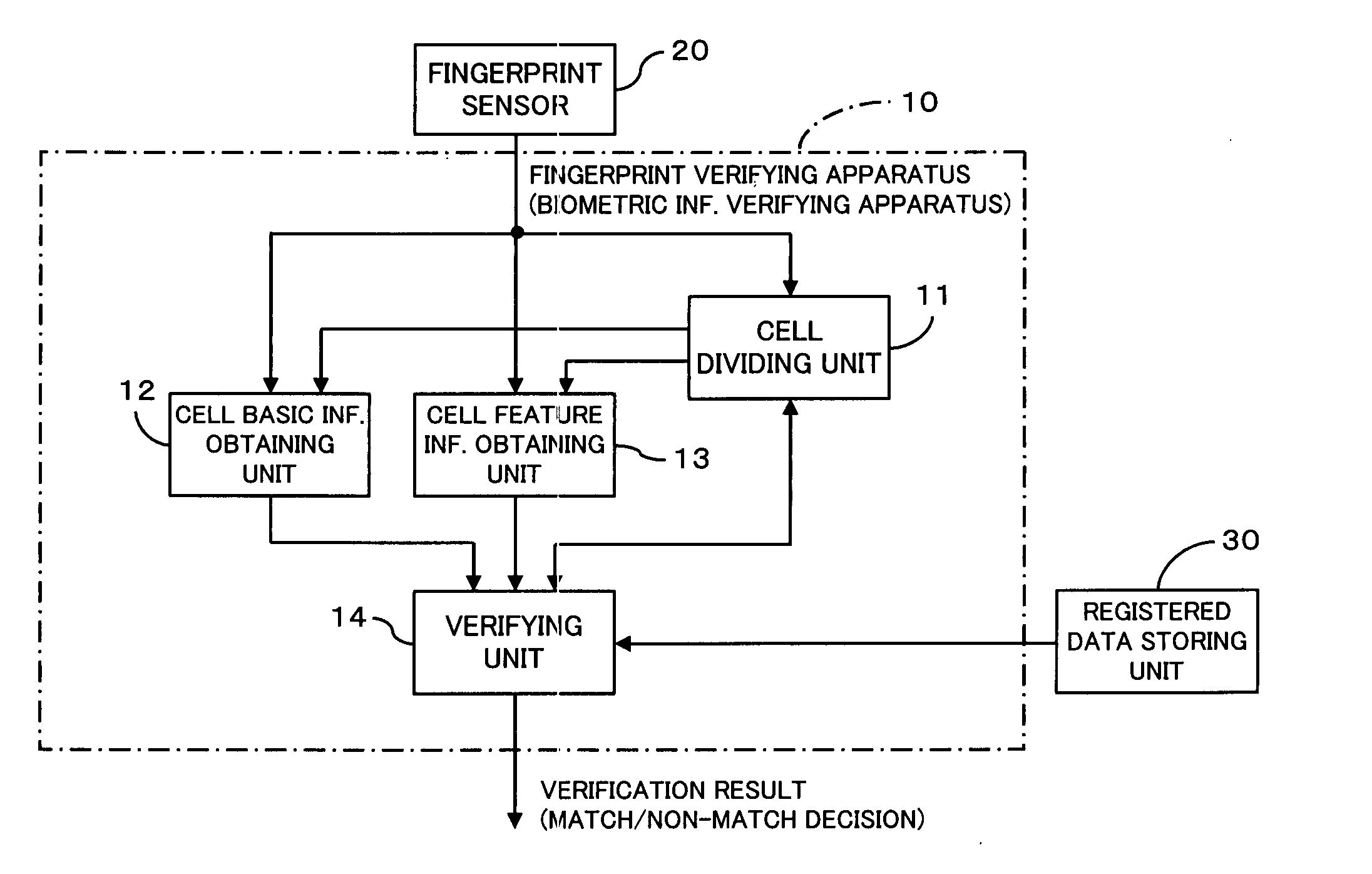
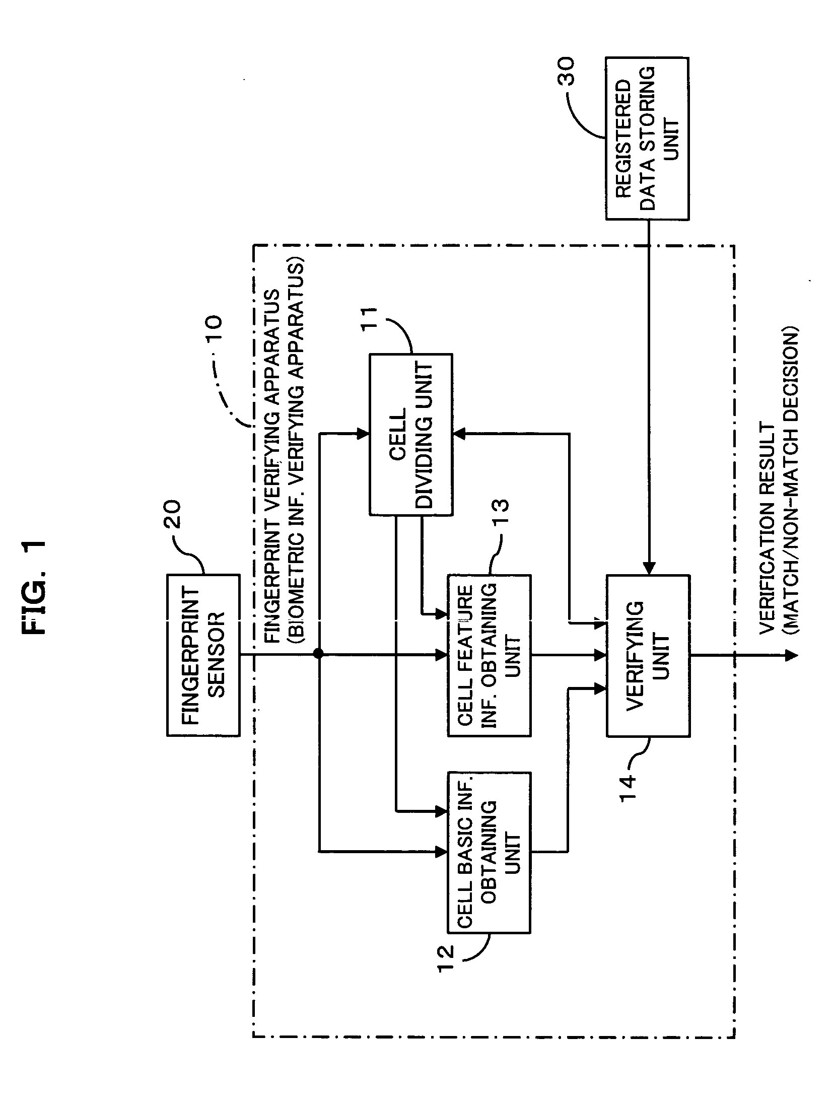
[0055] First of all, a description will be made of biometric information verifying apparatus (fingerprint verifying apparatus) according to a first through the present invention, referring to FIG. 1 which shows a functional construction of the apparatus.

[0056] As shown in FIG. 1, a fingerprint verifying apparatus 10 of the first through the sixth embodiment verifies a to-be-verified fingerprint image (a to-be-verified biometric information image; a ridge image of a biometric pattern), which is input by a user at the time of user verification, against a registered fingerprint image (a registered biometric information image; a ridge image of a biometric pattern), and the fingerprint verifying apparatus 10 is connected to the fingerprint sensor 20 and the registration data storing unit 30.

[0057] At user verification, the fingerprint sensor 20 is used to input the to-be-verified fingerprint image therethrough to the fingerprint verifying apparatus 10, and the registration data storing ...

first embodiment

[0071] [1] First Embodiment

[0072] Referring to FIG. 4 and FIG. 5, a description will now be made of an operation of a biometric information verifying apparatus (fingerprint verifying apparatus) 10 of a first embodiment of the present invention. FIG. 4 shows a flowchart indicating the operation; FIG. 5 shows procedures for aligning a registered fingerprint image and a to-be-verified fingerprint image by using ridge direction data obtained from the individual cells of those images.

[0073] As shown in FIG. 4, in the fingerprint verifying apparatus 10 of the first embodiment, when a user inputs a fingerprint image (to-be-verified fingerprint image) through a fingerprint sensor 20 at user verification (step S11), a cell dividing unit 11 decides a cell dividing position and divides the input to-be-verified fingerprint image, input through the fingerprint sensor 20, into cells which are the same as the cells used at cell division performed at user enrollment (step S12). The cell basic info...

second embodiment

[0081] [2] Second Embodiment

[0082] Referring to FIG. 6, FIG. 7, and FIG. 20, a description will now be made of an operation of a biometric information verifying apparatus (fingerprint verifying apparatus) 10 of a second embodiment of the present invention. FIG. 6 is a flowchart indicating the operation; FIG. 7A and FIG. 7B are an example fingerprint image which is divided into cells and the same example fingerprint image in which a cell division reference point is shifted, respectively; FIG. 20 is a view for use in describing a distance by which the cell dividing reference position is shifted.

[0083] As shown in FIG. 6, in the fingerprint verifying apparatus 10 of the second embodiment, when a user to be verified inputs a fingerprint image (to-be-verified fingerprint image) through a fingerprint sensor 20 at user verification (step S31), the cell dividing unit 11 decides a cell dividing position and divides the input to-be-verified fingerprint image, which is input through the finge...


PUM


Abstract

The apparatus greatly reduces the registered data amount and the verification computation amount required for user verification, in comparison with the verification using image information itself, and also decreases the false verification rate. The apparatus divides a biometric information image into cells, and extracts minutia information as well as cell basic information from the individual cells. After comparison of direction information of the individual cells of the registered data with direction information of the individual cells of the to-be-verified data, thereby aligning the registered fingerprint image and the to-be-verified fingerprint image, the apparatus compares the minutia information of corresponding cells between the registered data and the to-be-verified data to make a match/non-match decision. Such an apparatus is applicable to systems that employ pattern matching type image verification to perform user verification utilizing biometric information such as fingerprints, palm prints, blood vessel patterns, iris patterns, and facial images.

Description

BACKGROUND OF THE INVENTION [0001] 1. Field of the Invention [0002] The present invention relates to biometric information verifying apparatus which verify users by use of biometrics information such as fingerprints, palm prints, blood vessel patterns, iris patterns, facial images. The apparatus verifies biometric information images input by users at the time of verification against biometric information images registered in advance at enrollment. The invention particularly relates to biometric information verifying apparatus in which a pattern matching method of image verification is employed. [0003] 2. Description of the Related Art [0004] Pattern matching is a method commonly used in extracting human figure images, facial images, or specific object images such as vehicles, from picture images. The method is also widely used in user verification utilizing biometric information such as fingerprints, palm prints, blood vessel patterns, iris patterns, and facial images. The applicati...

Claims


Application Information

Patent Timeline
IPC IPC(8): G06K9/00A61B5/117G06T7/00
CPCG06K9/00087G06K9/0008G06V40/1359G06V40/1365G06F18/00
Inventor SHINZAKI, TAKASHI
Owner FUJITSU LTD
Why Eureka
Try Eureka