Measuring instrument for biosensor and measuring method using same

a biosensor and measuring instrument technology, applied in the field of measuring devices for biosensors, can solve the problems of deterioration in sensor responsibility and difficulty in reducing the amount of samples needed for measuremen

Inactive Publication Date: 2005-08-11
PANASONIC CORP
View PDF3 Cites 98 Cited by
  • Summary
  • Abstract
  • Description
  • Claims
  • Application Information

AI Technical Summary

Problems solved by technology

There has therefore been a problem with this sensor in that, as a hematocrit value increases, blood viscosity becomes higher and blood cells are adsorbed in a greater degree to an electrode and an enzyme, having the effect of causing deterioration in sensor responsibility.
However, there has been a problem with the technique of Japanese Laid-Open Pa

Method used


Image

  • Measuring instrument for biosensor and measuring method using same
  • Measuring instrument for biosensor and measuring method using same
  • Measuring instrument for biosensor and measuring method using same

Examples


embodiment 1

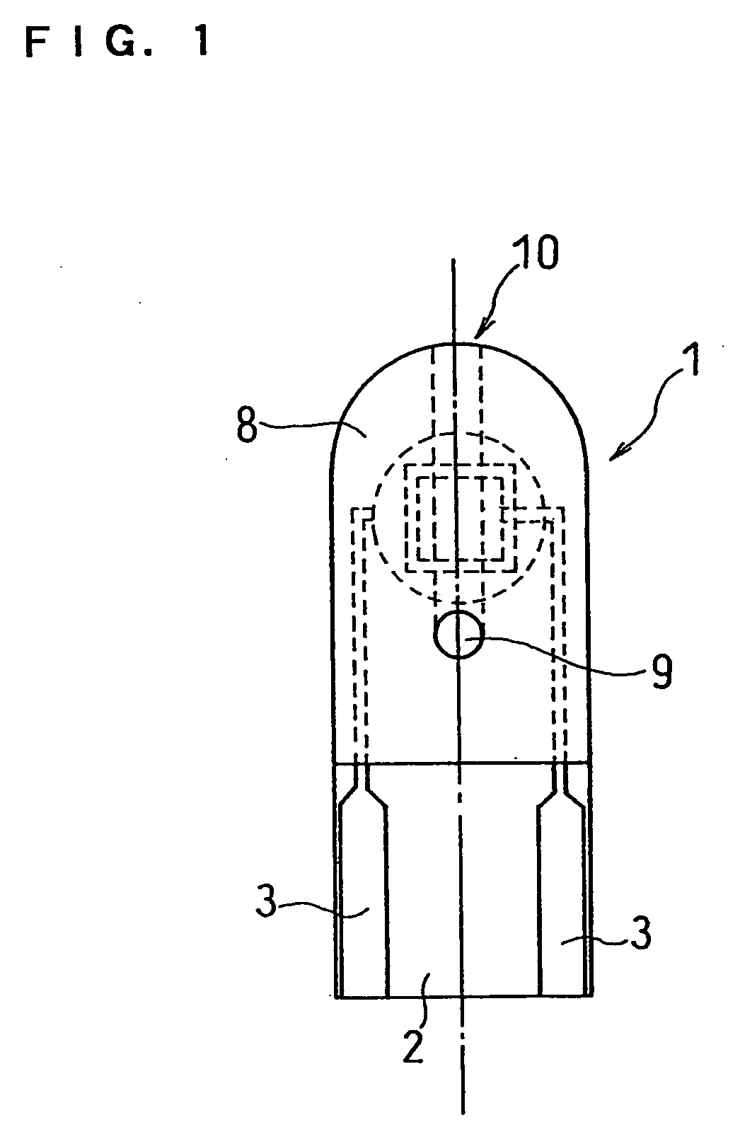
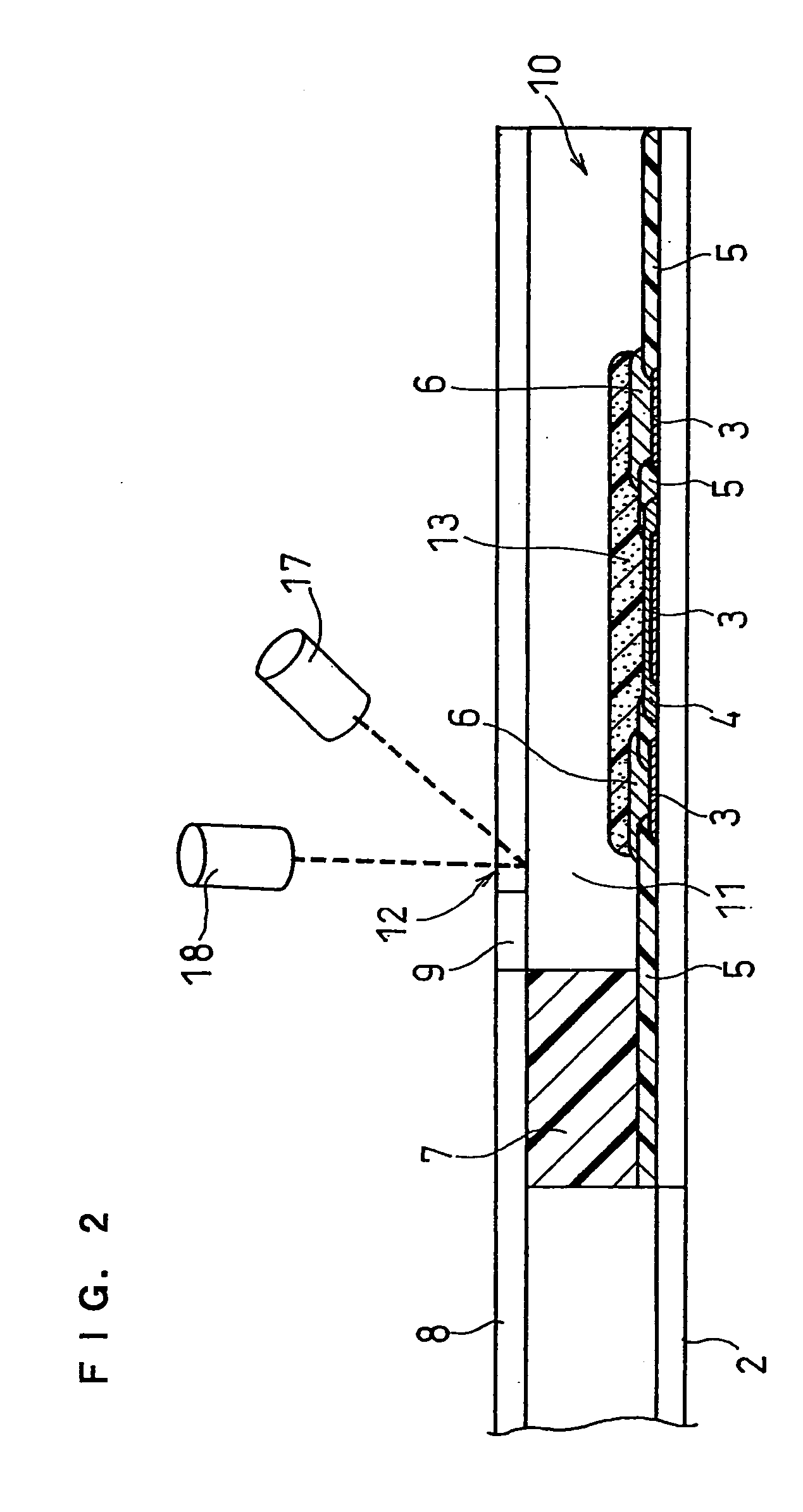
[0065]FIG. 1 is a top plan view showing the whole of a biosensor 1 usable in the present invention. In FIG. 1, the center line was shown with a dash-dotted line. FIG. 2 is a cross sectional view of the biosensor cut on the dash-dotted line of FIG. 1. A method for producing a biosensor in accordance with the present invention is described with reference to FIGS. 1 and 2.

[0066] First, a silver paste is printed on an insulting base plate 2 made of a resin (polyethylene terephthalate (PET)) by screen printing to form a lead 3. A paste including a resin binder and a conductive carbon is printed to form a measurement electrode 4, and then an insulating paste (resist) is printed to form an insulating layer 5. Finally, the paste including a resin binder and a conductive carbon is again printed to form a counter electrode 6. Herein, the insulating layer 5 regulates the area of the measurement electrode 4.

[0067] Subsequently, a reagent section 13 including an enzyme and an electron mediator...

embodiment 2

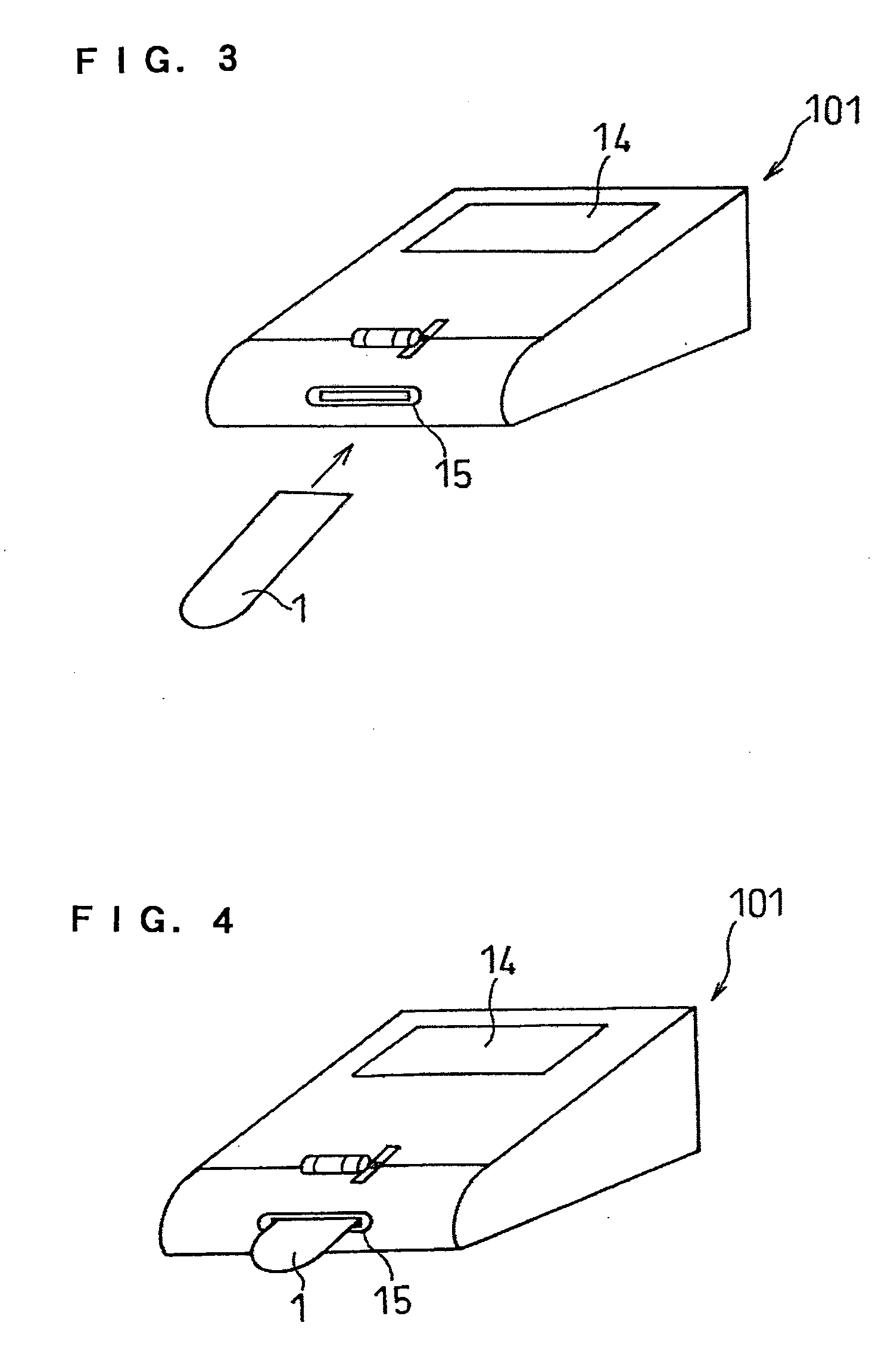
[0069]FIG. 3 is a perspective view showing the whole of a biosensor in accordance with an embodiment of the present invention. In FIG. 3, a supporting section 15 is formed in a measuring device 101 for a biosensor, and the biosensor 1 is inserted into this section to be installed and supported. FIG. 4 showed how the biosensor 1 has been installed. With the biosensor 1 inserted into the supporting section 15, preparation for measurement with the measuring device 101 is completed. A display section 14 is arranged in the measuring device 101.

[0070] Subsequently, the tip of a finger is stung using a lancet, and after confirmation that blood is oozed from the finger, the blood is brought into contact with the sample supply port 10 of the biosensor 1 so as to be introduced into the biosensor 1. The blood introduced in the biosensor 1 reacts with an enzyme in the reagent section 13. Further, it is possible to determine a volume ratio between a solid and a liquid in the blood by irradiatio...

embodiment 3

[0072]FIG. 5 is a diagram showing the configuration of the measuring device 101 in accordance with the present invention, including the biosensor 1. A measuring method of a specific substance in accordance with the present invention is described with reference to FIG. 5.

[0073] First, the biosensor 1 is inserted into the supporting section 15 in the measuring device 101 and then fixed therein (the step (a)). The inner side of the supporting section 15 is provided with a connecting terminal 16 in a position in contact with the lead 3 of the biosensor 1, and the contacting terminal 16 is connected to the lead 3 by the installation of the biosensor 1 (the step (b)).

[0074] Upon completion of this step, a sample is supplied from the sample supply port (numeral 10 in FIG. 2) of the biosensor 1 (the step (c)). A light source 17 is then turned on (the step (d)). At this time, the light source 17 is arranged at an upper portion over the biosensor 1 inserted in the measuring device 101, i.e....


PUM


Abstract

There are provided a measuring device for a biosensor, capable of performing a simple, accurate and short-time measurement of a specific substance in a sample without being affected by physical properties of a sample, and a measuring method. In the measuring device for a biosensor in accordance with the present invention, a biosensor is used which includes: a sample supply port; an electrode system having a measurement electrode and a counter electrode; and a portion where a sample can be irradiated with light in at least part of a sample supply pathway, to detect electrical and optical variations in the sample and determine a physical factor of the sample, so that a measurement value can be corrected.

Description

TECHNICAL FIELD [0001] The present invention relates to a measuring device for a biosensor, capable of performing a simple, accurate and short-time measurement of the concentration of a specific substance contained in a sample, and to a measuring method using the device. BACKGROUND ART [0002] As a biosensor capable of performing a simple and accurate measurement of a specific substance in a sample without dilution or stirring of the sample, there has hitherto been a biosensor proposed, for example, in Japanese Laid-Open Patent Publication No. Hei 3-202764. [0003] This biosensor is obtained by forming an electrode system on an insulating base plate, and then forming on the electrode system an enzyme reaction layer with a mixture of a hydrophilic polymer, oxidoreductase and an electron mediator. Variations in substance concentration due to a reaction of the oxidoreductase, the electron mediator and the sample are then electrochemically detected with the electrode system to measure a s...

Claims


Application Information

Patent Timeline
IPC IPC(8): C12M1/34G01N27/327G01N33/487G01N33/86
CPCG01N27/3274
Inventor MIYASHITA, MARIKOTANIIKE, YUKOYOSHIOKA, TOSHIHIKO
Owner PANASONIC CORP
Why Eureka
Try Eureka