Temporary vascular filter, guide wire

a technology of vascular filter and guide wire, which is applied in the field of vascular filter, can solve the problems of inability to adjust during the procedure, the operator's ability to use balloon catheters and stent devices involving the same procedure, and the inability to achieve the use of filter protection in place, so as to achieve the effect of reducing complexity and facilitating modification of relative spacing between the filter and the lesion location

Inactive Publication Date: 2005-08-11
CR BARD INC
View PDF67 Cites 64 Cited by
  • Summary
  • Abstract
  • Description
  • Claims
  • Application Information

AI Technical Summary

Benefits of technology

[0010] The apparatus and method of the present invention minimizes the complexity associated with manipulating a vascular filter during an angioplasty or stent placement procedure by incorporating the filter on a catheter guide wire such that the guide wire performs the dual functions of guiding the catheter to a stenosed location, and filtering dislodged particles flowing downstream of the treated area. Moreover, because the guide wire operates independently of the catheter, relative spacing between the filter and the lesion location may be easily altered, and exchanges of various devices over the wire are possible.

Problems solved by technology

While conventional vena caval filters work well for their intended purposes, they suffer from the disadvantages associated with damaging the inner vessel wall through the inherent penetrating nature of the hooks, and blockage caused over time as the filter becomes endothelialized with the blood vessel inner wall or as recurrent blood clots obstruct blood flow through the filter.
The extra lines and wires typically create added complexity for the operator.
Because the conventional filters are mounted to the distal ends of the respective catheters, adjustments during the procedure typically cannot be made.
Furthermore, the use of balloon catheters and stent devices involving the same procedure could not be achieved with filter protection in place.

Method used


Image

  • Temporary vascular filter, guide wire
  • Temporary vascular filter, guide wire
  • Temporary vascular filter, guide wire

Examples


first embodiment

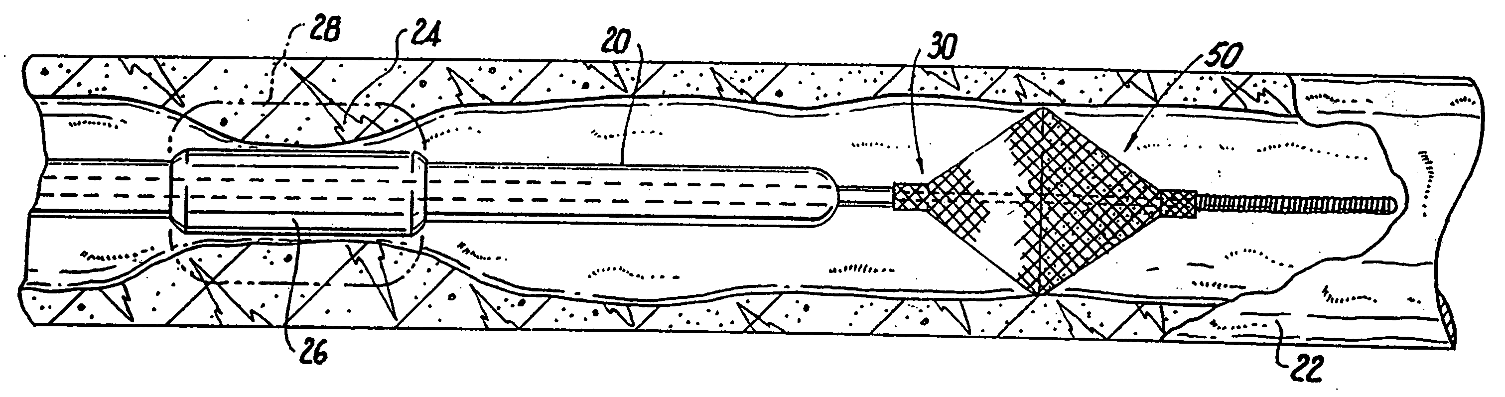
[0034] In order to reach the lesioned area, however, the catheter must be able to follow a trackable path defined by a catheter guide wire. In accordance with the present invention, a catheter guide wire, generally designated 30, provides a trackable path for a catheter and includes a distally disposed collapsible filter 50 to trap particulate matter dislodged by the catheter 20 during treatment of the stenosis.

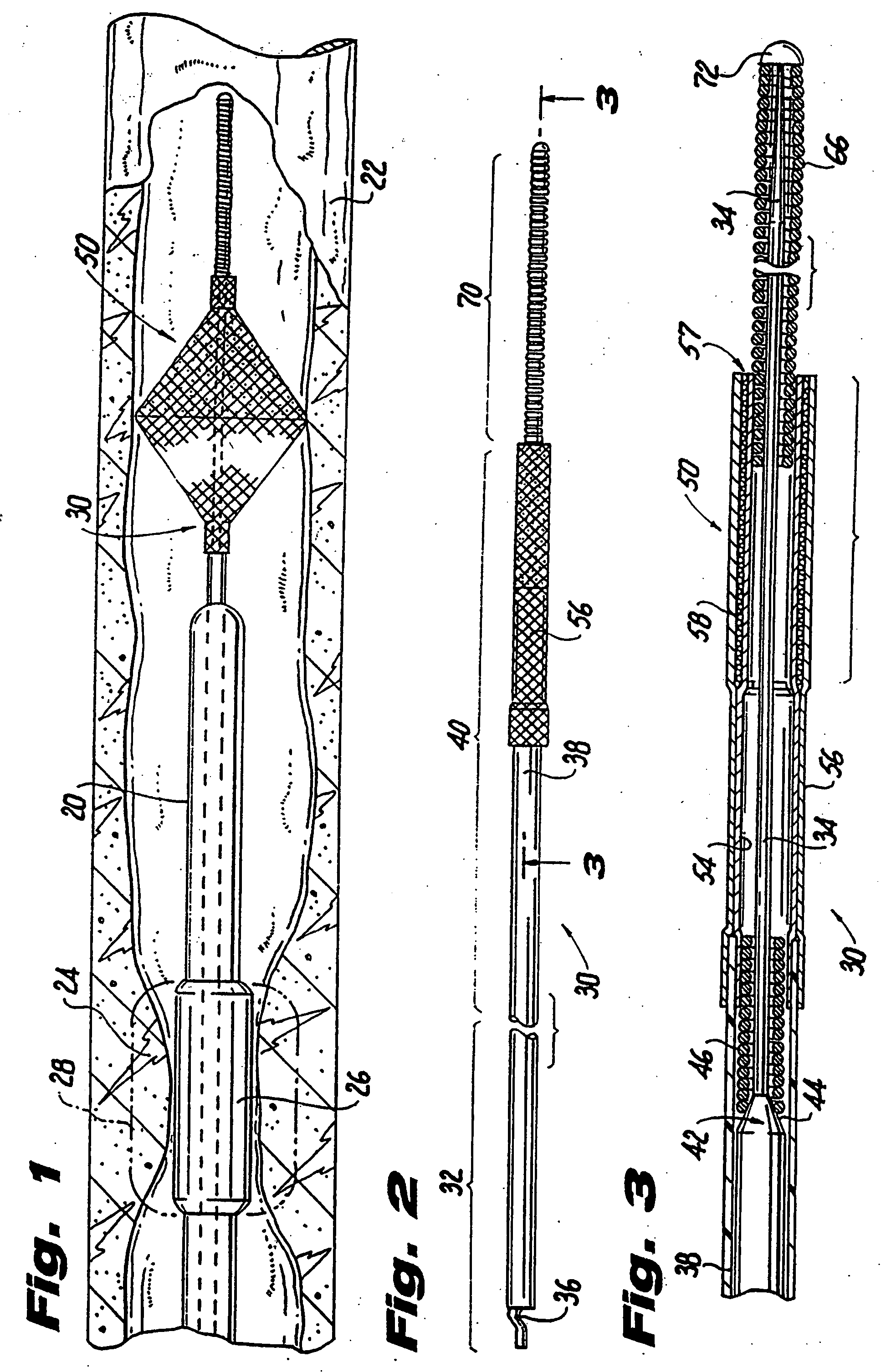
[0035] Referring now to FIGS. 2 through 5, the guide wire 30 includes a proximal section 32 comprising a solid core wire 34 having a wave-shaped proximal end 36 (FIG. 2). A tubular shaft 38 is coaxially disposed around the core wire and includes an outer diameter equal to the nominal size of the guide wire. The inner diameter of the tube is sized to form a friction fit with the core wire proximal end when slid thereover during insertion and removal of the guide wire. The shaft functions to deploy and retract the filter device, and to guide and support the catheter 20, and to ...

embodiment 80

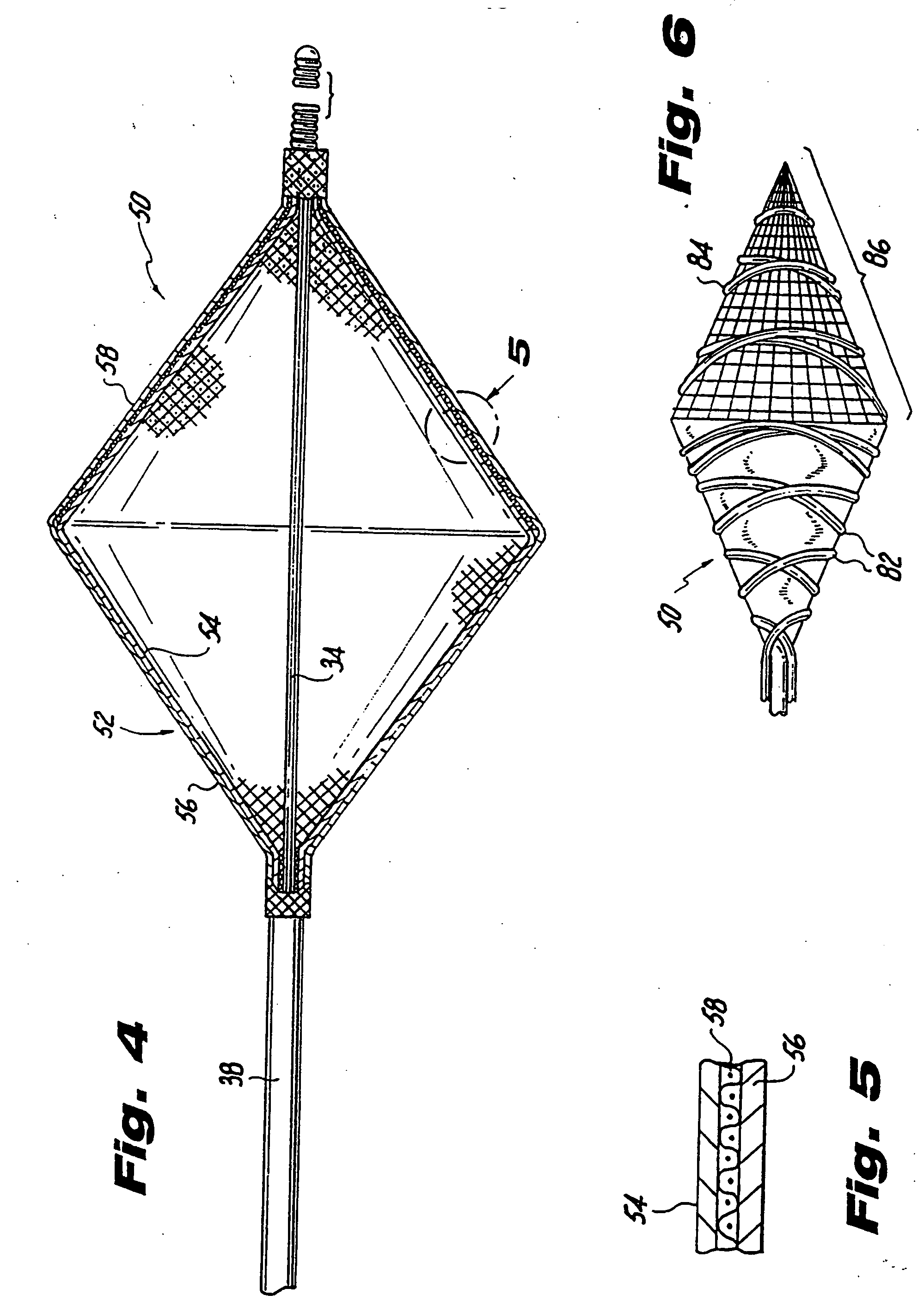
[0046] The alternative filter embodiment 80 may be fabricated similar to the procedure above with only minor variations. Conveniently, because of the composite nature and relatively high pic density of the metallic / polymeric braid, only one braiding step is required. After the final braid, the polymeric strands at the proximal end are mechanically or thermally cut away, and the filaments fused at the large diameter of the formed cone to form the collection cavity and to allow for greater blood flow.

[0047] In operation, the guide wire 30 may be advanced through a vascular system in any conventional manner to establish a path for the catheter to track over. Generally, as shown in FIG. 1, the guide wire is inserted through the lesion and disposed downstream of the lesion 24 a variably selected distance. The distance selected by the operator may be conveniently adjusted merely by further advancing or slightly withdrawing the guide wire. This provides the highly desirable capability of e...


PUM

PropertyMeasurementUnit
lengthaaaaaaaaaa
sizeaaaaaaaaaa
lengthaaaaaaaaaa

Abstract

A vascular filter guide wire is disclosed for directing precision placement of a catheter proximate a blood vessel lesion and filtering particulate matter dislodged by treatment of the vessel. The guide wire includes an actuating mechanism, an elongated flexible core wire having a proximal end mounted to the actuating mechanism and a distal end for insertion through a vasculature to a position downstream of the restriction. A tubular flexible shaft is slidably disposed telescopically along the core wire and includes a proximal portion affixed to the actuating mechanism in movable relation to the core wire. The guide wire includes a collapsible filter at its proximal end to the distal portion of the shaft and, at its distal end, to the core wire. The filter deploys radially in response to axial movement of the core wire relative to the shaft so that it can trap particulate matter arising from treatment of the lesion.

Description

FIELD OF THE INVENTION [0001] The invention relates to vascular filters intended to capture embolic particles, by means of filtration, that may arise from the treatment of diseased blood vessels. BACKGROUND OF THE INVENTION [0002] Percutaneous intravascular treatment of diseased blood vessels, such as angioplasty or stent placement procedures, may result in the dislodgment of loose plaque or thrombus which then migrate downstream. Since any such particles may become lodged in other vessels, effectively preventing blood from passing into the organ which that vessel supplies, and potentially causing serious end-organ damage which may be difficult or impossible to reverse, effective avoidance of this complication is extremely important. [0003] One of the early methods of removing residual matter resulting from an angioplasty procedure using a balloon catheter involved maintaining the balloon in an inflated state while performing the intended intervention on the blood vessel. In this ma...

Claims


Application Information

Patent Timeline
Patent Type & Authority Applications(United States)
IPC IPC(8): A61F2/01
CPCA61F2/01Y10T29/49604A61F2002/011A61F2002/016A61M25/09A61M2025/09183A61F2002/018A61F2230/0006A61F2230/0021A61F2230/005A61F2230/0067A61F2230/0086A61F2230/0093A61F2230/0097Y10T29/49801A61F2/013A61F2/0108A61F2/011A61F2/012
Inventor GRAY, WILLIAMGAMBALE, RICHARD A.
Owner CR BARD INC
Why Eureka
Try Eureka