Method of and apparatus for measuring jitter and generating an eye diagram of a high speed data signal

a high-speed data and eye diagram technology, applied in the direction of generating/distributing signals, instruments, horology, etc., can solve the problems of receiving signals at a non-optimal sampling point, various forms of jitter not well characterized with eye diagrams, and case errors in the transmission of data

Inactive Publication Date: 2005-08-11
ANRITSU CORP
View PDF9 Cites 37 Cited by
  • Summary
  • Abstract
  • Description
  • Claims
  • Application Information

AI Technical Summary

Benefits of technology

[0015] The method includes sampling the input signal at a plurality of sampling points, wherein the input signal is sampled dependent on the synthesized signal frequency. The method comprises adjusti

Problems solved by technology

However, the various forms of jitter are not well characterized with eye diagrams.
This deviation may case errors in the transmission of data, particularly when the data is transmitted at high speeds.
ISI is caused by data path propagation delay which is a function of past data history and can be caused by transmission line reflections.
DCD can be caused by propagation delay differences between low to high and high to low transitions.
Jitter is a problem of particular importance in digital communication systems and can cause the received signal to be sampled at a non-optimal sampling point.
This increases the bit-error ratio at the receiver and thus limits the data rate.
Jitter makes this task significantly more difficult.
Time delay generators are adversely influenced b

Method used


Image

  • Method of and apparatus for measuring jitter and generating an eye diagram of a high speed data signal
  • Method of and apparatus for measuring jitter and generating an eye diagram of a high speed data signal
  • Method of and apparatus for measuring jitter and generating an eye diagram of a high speed data signal

Examples


Embodiment Construction

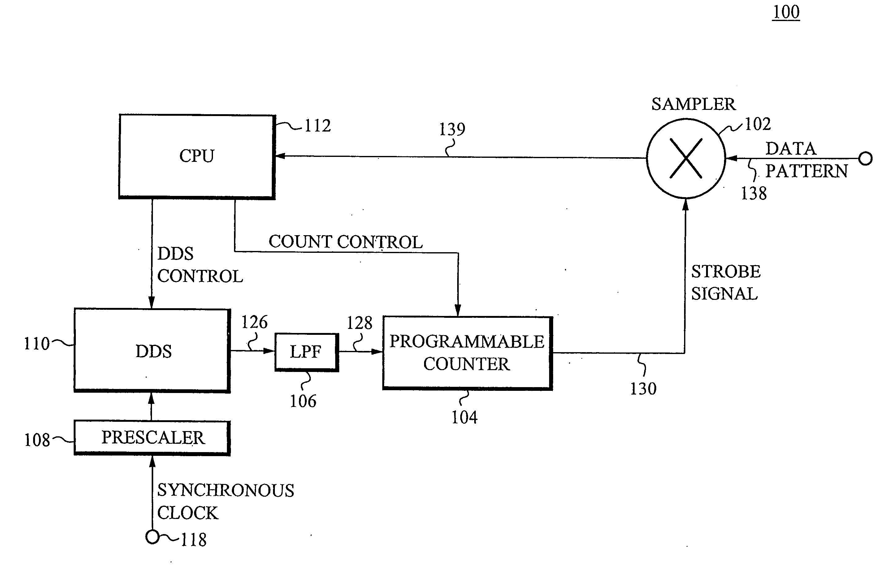
[0021] The present invention discloses a method and apparatus for analyzing high-speed data signals and arranging the analyzed data. In general, the present invention performs sampling of incoming signals by utilizing a synthesized signal generated from the reference clock frequency and a counter to generate sampler strobe signals. The present invention uses a technique for arranging the sampled data to form an eye diagram. The timing of the sample events is preferably controlled by the programmable output frequency of a Direct-Digital-Synthesizer (DDS) and the count interval of a programmable counter. To perform an eye-diagram measurement, the DDS output is set to a frequency that is a fraction of the clock frequency. This frequency is chosen such that appropriate arrangement of the sample points produces an eye diagram having the desired resolution. In addition, the present invention is capable of measuring the Duty Cycle Distortion (DCD) and Intersymbol Interference (ISI) jitter ...


PUM


Abstract

A sampling system is disclosed which measures high speed data signals by performing sampling events at intervals determined by a programmable DDS output frequency and a programmable counter. The reference frequency of the DDS is that of a clock signal that is synchronous with the data signal to be measured. The present invention is able to arrange the sample points to form an eye diagram of the input signal. In addition, the present invention is capable of sampling synchronously with the data clock and controlling the phase of the synthesized signal such that the samples are localized around the rising and falling edges of the data waveform. The present invention is thereby able to determine the location of the edges of the data signal and analyze the deterministic jitter of the waveform.

Description

FIELD OF THE INVENTION [0001] The present invention is related to measuring high speed data signals in general, and to a method and apparatus for generating an eye diagram from high speed data signals and measuring jitter components in the high speed data signals. BACKGROUND OF THE INVENTION [0002] Equivalent time sampling oscilloscopes use undersampling of periodic high speed data waveforms to produce an eye diagram. An eye diagram is a superposition of the various logic states of a data waveform and is a common way to assess the integrity of the signal. Particularly, an eye diagram is a useful means for readily obtaining information regarding voltage swing and transition time of the incoming data. However, the various forms of jitter are not well characterized with eye diagrams. [0003] Jitter is the general term used to describe the noise or uncertainty in the period of incoming data in a communications system. In an ideal communications system, bits arrive at time increments that...

Claims


Application Information

Patent Timeline
IPC IPC(8): G06F1/12G06F3/05
CPCG06F3/05G06F1/12
Inventor STICKLE, KYLE
Owner ANRITSU CORP
Why Eureka
Try Eureka