

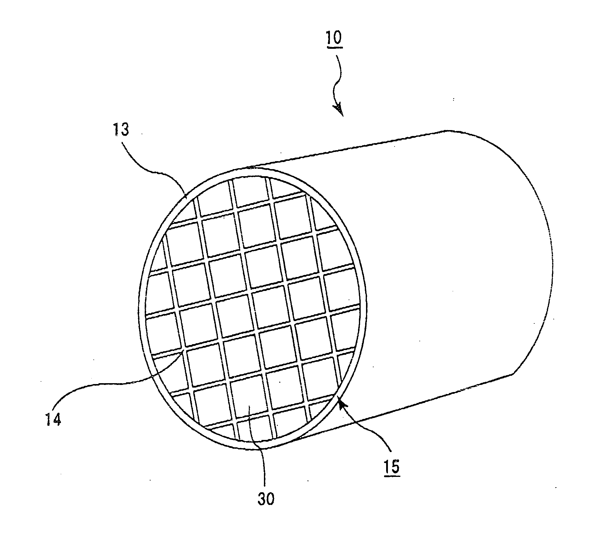
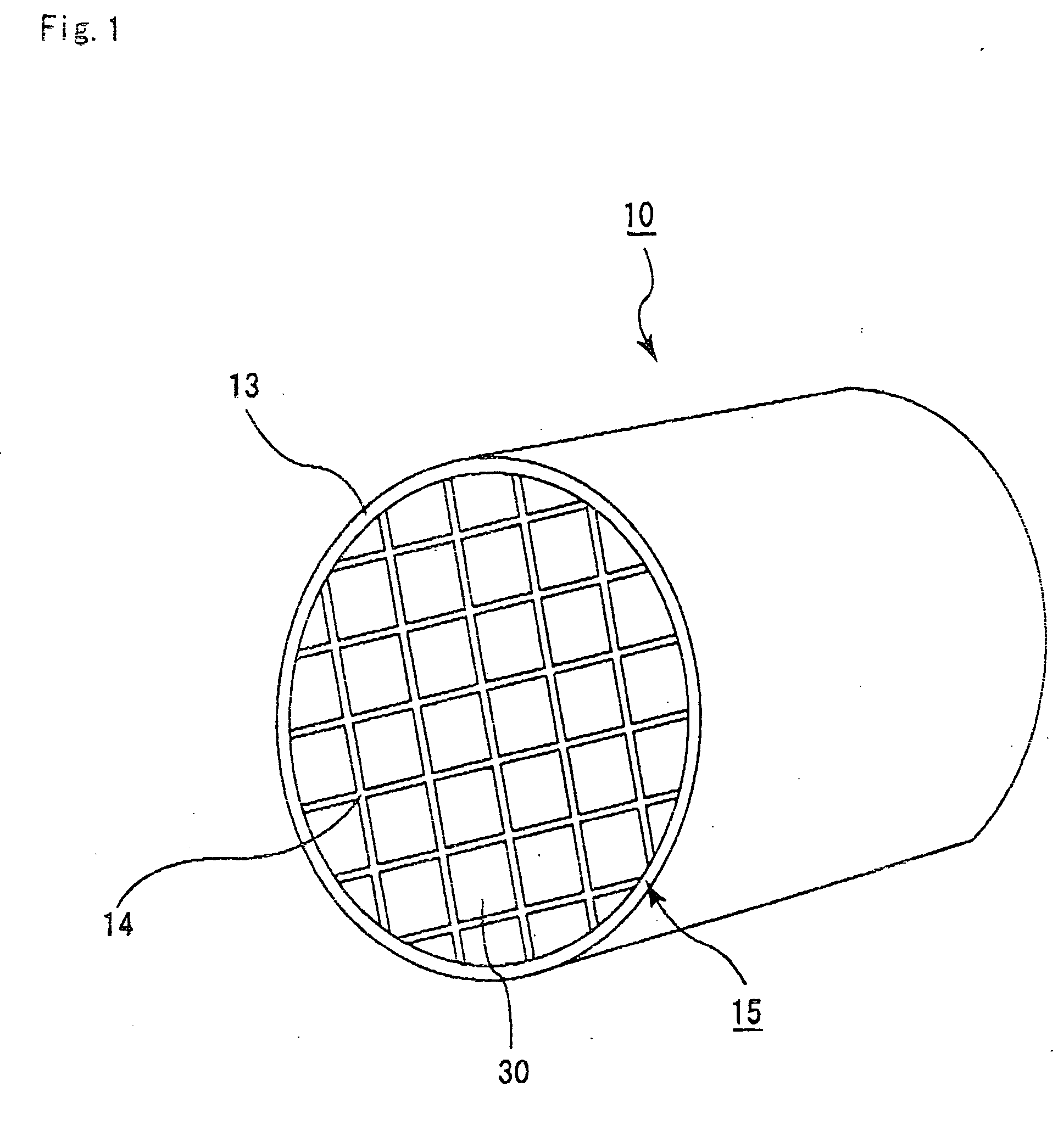
Ceramic structure, method of manufacturing ceramic structure, and device for manufacturing ceramic structure
a ceramic structure and ceramic technology, applied in the direction of turning machines, turning machine accessories, drawing profiling tools, etc., can solve the problems of harmful to the environment and human body of particles in exhaust gas of internal combustion engines of vehicles, such as buses or tracks, construction machines or the lik
- Summary
- Abstract
- Description
- Claims
- Application Information
AI Technical Summary
Benefits of technology
Problems solved by technology
Method used
Image

Examples
example 1
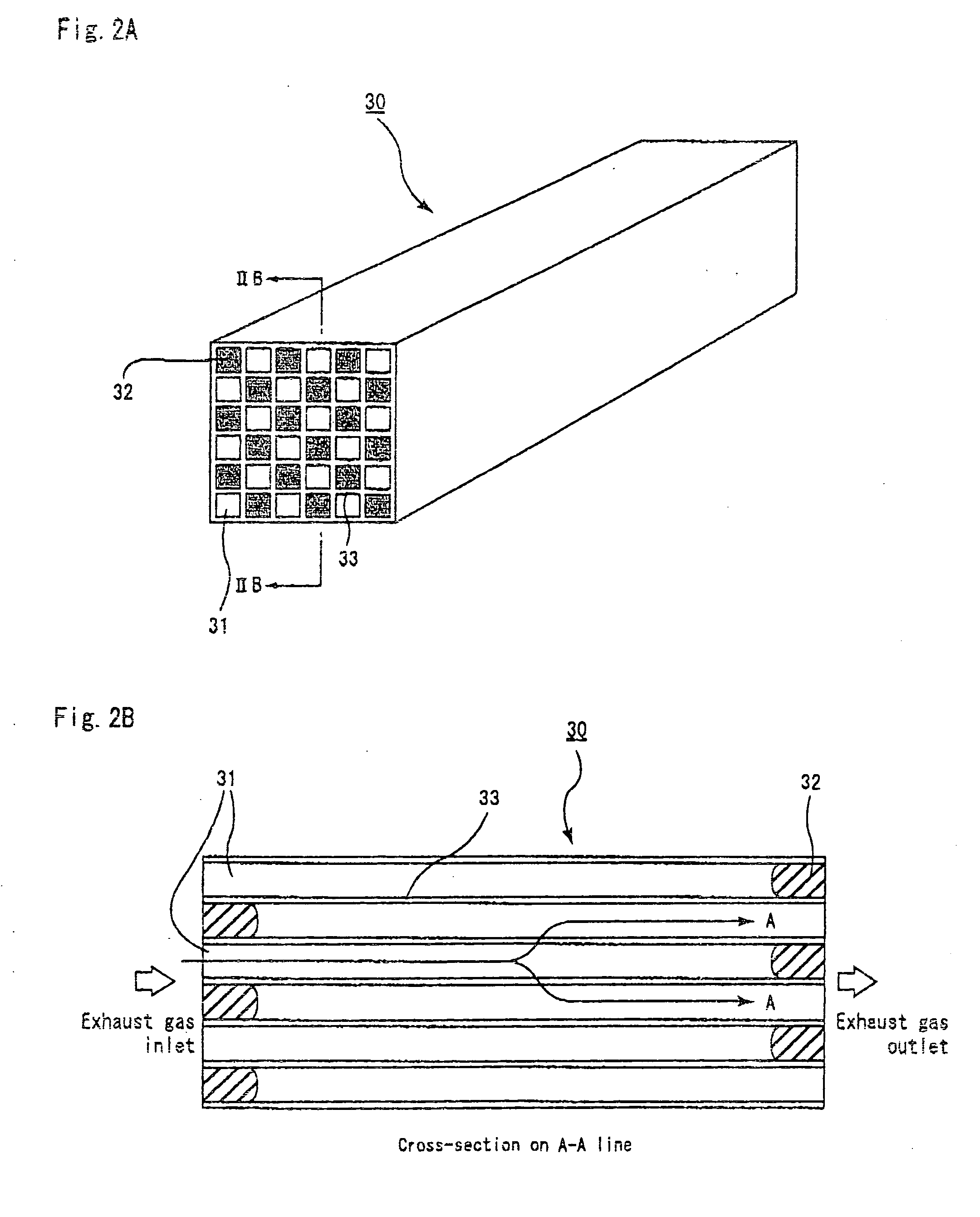
[0116] (1) 70 wt % of α type silicon carbide powder with an average particle size of 10 μm, 30 wt % of β type silicon carbide powder with an average particle size of 0.7 μm, 5 wt % of methyl cellulose, 4 wt % of a dispersion agent, and 20 wt % of water were blended and evenly mixed to prepare a mixed composition as a source material. The mixed composition was filled in an extrusion molding machine and a ceramic compact with a honeycomb shape was prepared at the extrusion speed of 2 cm / min. The ceramic compact has a shape approximately similar to that of the porous ceramic member 30 shown in FIG. 3, and has a size of 33 mm×33 mm×254 mm, with the number of through holes being 31 / cm2 and the thickness of the partitions being 0.35 mm. In this example, the longitudinal length (254 mm) of the porous ceramic member 30 is obtained by measuring the distance between the end face SI on the inlet side and the end face SO on the outlet side and is represented in FIGS. 6A and 6B by the length of ...
examples 2 to 9 and reference examples 1 to 6
[0123] The ceramic structures 10 of porous silicon carbide were manufactured in the same way as done for Example 1, except for the changes in the amount of warping of the porous ceramic members 30 and in the length LM of the sealer-paste unfilled portion at either end portion of the ceramic member assembly 16 measured after press fitting the sealer paste 1400 as shown in Table 1.
[0124] The amount of warping of the porous ceramic members 30 was adjusted by changing the amount of warping of the degreasing / baking device. The length from the end face of the sealer-paste unfilled portion was adjusted by changing the amount of the sealer paste 1400 to be press-fitted.
examples 10 to 12 and reference examples 7 and 8
[0125] The ceramic structures 10 of porous silicon carbide were manufactured in the same way as done for Example 1, except that the amount of warping of the porous ceramic members 30 was changed, that the length from the end face of the sealer-paste unfilled portion at either end portion of the ceramic member assembly 16 after press fitting of the sealer paste 1400 was changed, and that the thickness of the spacers 142 made of a cardboard was changed to 2.0 mm, as shown in Table 1.
[0126] The amount of warping of the porous ceramic members 30 was adjusted by changing the amount of warping of the degreasing / baking device. The length from the end face of the sealer-paste unfilled portion was adjusted by changing the amount of the sealer paste 1400 to be press-fitted.
PUM
| Property | Measurement | Unit |
|---|---|---|
| longitudinal length | aaaaa | aaaaa |
| particle size | aaaaa | aaaaa |
| particle size | aaaaa | aaaaa |
Abstract
Description
Claims
Application Information