Image display device employing selective or asymmetrical smoothing

a display device and selective or asymmetrical technology, applied in static indicating devices, cathode-ray tube indicators, instruments, etc., can solve the problems of difficult to fabricate a display screen with extremely small pixels, lines may become too faint to be easily seen, and letters may become difficult to read, so as to improve the visibility of dark lines

Inactive Publication Date: 2005-08-18
MITSUBISHI ELECTRIC CORP
View PDF12 Cites 17 Cited by
  • Summary
  • Abstract
  • Description
  • Claims
  • Application Information

AI Technical Summary

Benefits of technology

[0020] An object of the present invention is to enhance the visibility of dark lines and dots displayed on a bright background.
[0021] Another object of the invention is to reduce colored tinges at the edges of white objects in a color image.
[0022] Another object is to suppress ringing effects without unnecessary loss of edge sharpness.
[0028] This method enhances the visibility of dark lines and dots because these parts of the image are not smoothed.
[0032] This method can reduce colored tinges by employing filtering characteristics that move the luminance centroids of the different primary colors closer together.
[0036] This method reduces ringing at edges where ringing occurs, without unnecessary loss of sharpness at edges where ringing does not occur.

Problems solved by technology

Although there is a trend toward increasing resolution in matrix-type displays, it is difficult to fabricate a display screen with extremely small pixels, especially when each pixel comprises three separate cells.
Another problem occurs when dark (for example, black) lines or letters are displayed on a bright (for example, white) background, to mimic the appearance of a printed page.
When fine dark lines formed from dark dots are displayed on a bright background, the lines may become too faint to be seen easily.
When dark text is displayed in a small font on a bright background, the letters may become difficult to read.
While this filtering process prevents the apparent decrease in size of dark dots and lines on bright backgrounds, it also leads to a certain loss of sharpness.
A further problem occurs when the input analog signals are transmitted to the image display device through cables with imperfect impedance matching, leading to ringing phenomena. FIG. 12 illustrates the ringing effect in the display of a single white dot of arbitrary width, the horizontal axis indicating horizontal position on the display screen, the vertical axis indicating luminance.

Method used


Image

  • Image display device employing selective or asymmetrical smoothing
  • Image display device employing selective or asymmetrical smoothing
  • Image display device employing selective or asymmetrical smoothing

Examples


first embodiment

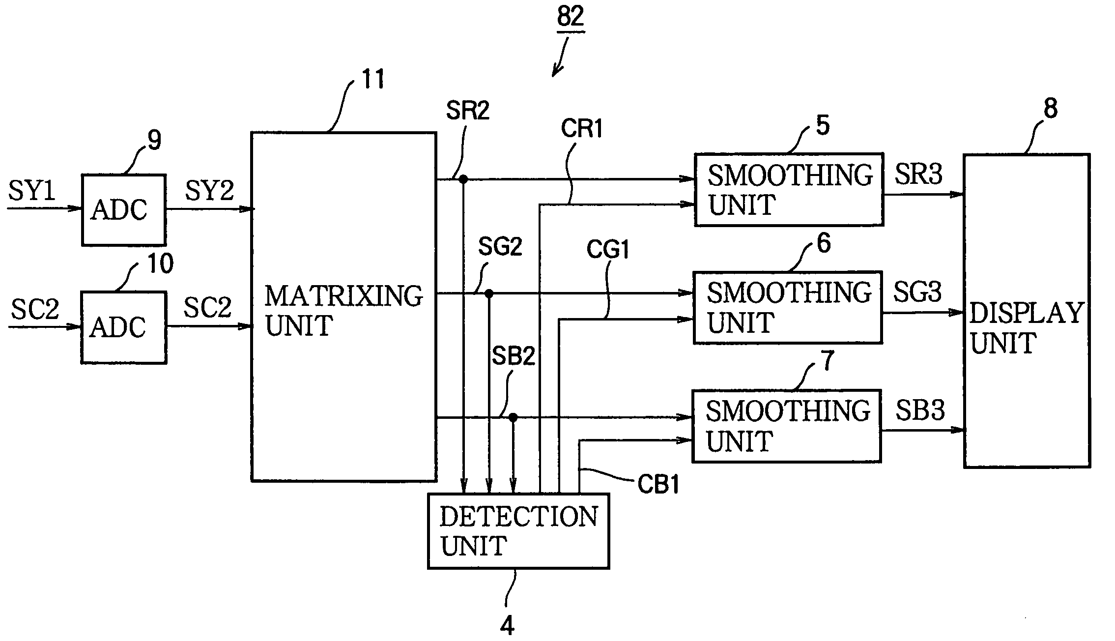
[0089] Referring to FIG. 14, the invention is an image display device 81 comprising analog-to-digital converters (ADCs) 1, 2, 3, a detection unit 4, smoothing units 5, 6, 7, and a display unit 8. The analog-to-digital converters 1, 2, 3 convert analog input signals SR1, SG1, SB1 to digital signals SR2, SG2, SB2 representing red, green, and blue image data, respectively. The detection unit 4 receives these digital signals SR2, SG2, SB2 and generates corresponding control signals CR1, CG1, CB1. The smoothing units 5, 6, 7 filter the digital signals SR2, SG2, SB2 according to the control signals CR1, CG1, CB1. Each smoothing unit comprises, for example, a plurality of internal filters with different filtering characteristics, and a switch that selects one of the internal filters according to the corresponding control signal. The display unit 8 displays the resulting filtered signals SR3, SG3, SB3.

[0090] As a variation of the first embodiment, FIG. 15 shows an image display device 82 th...

second embodiment

[0133] As a variation of the second embodiment, FIG. 29 shows an image display device 86 that receives an analog luminance signal SY1 and an analog chrominance signal SC1 instead of analog red-green-blue input signals. This image display device 86 is similar to the image display device 82 in FIG. 15, except that the detection unit 4 is replaced by a detection unit 14 that receives the digitized luminance signal SY2 directly from analog-to-digital converter 9. This detection unit 14 is identical to the detection unit 14 in the image display device 85. The analog-to-digital converters 9, 10, matrixing unit 11, and smoothing units 5, 6, 7 are similar to the corresponding elements in FIGS. 15 and 28, so further description will be omitted.

[0134] As another variation of the second embodiment, FIG. 30 shows an image display device 87 that receives an analog composite signal SP1. This image display device 87 is similar to the image display device 83 in FIG. 16, except that the detection un...

third embodiment

[0158] By operating as described above, the third embodiment is able to execute smoothing processing only on image data representing bright parts of the image that are adjacent to edges in the image.


PUM


Abstract

An image display device includes a smoothing unit that filters the image data to be displayed. According to one aspect of the invention, only bright parts of the image that are adjacent to dark parts are smoothed, thereby improving the sharpness of dark dots and lines displayed on a bright background. According to another aspect, different primary colors are smoothed with different characteristics, enabling unwanted colored tinges to be removed from the edges of white areas. According to still another aspect, smoothing moves the luminance centroids of all primary colors in a direction in which the display screen is scanned, to reduce ringing effects without needless loss of edge sharpness.

Description

[0001] This application is a Divisional of co-pending application Ser. No. 09 / 846,384, filed on May 2, 2001, and for which priority is claimed under 35 U.S.C. § 120; and this application claims priority of Application Nos. 2000 / 220318 and 2000 / 228690 filed in Japan on Jul. 21, 2000 and Jul. 28, 2000 under 35 U.S.C. § 119; the entire contents of all are hereby incorporated by reference.BACKGROUND OF THE INVENTION [0002] The present invention relates to an image display device and method, more particularly to a method of digitally processing an image signal to clarify lines, dots, and edges. [0003] Images are displayed physically by a variety of devices, including the cathode-ray tube (CRT), liquid-crystal display (CRT), plasma display panel (PDP), light-emitting diode (LED) display, and electroluminescence (EL) panel. To display color images, these devices have separate light-emitting components for three primary colors, normally red, green, and blue. [0004] In a CRT display, the sep...

Claims


Application Information

Patent Timeline
Patent Type & Authority Applications(United States)
IPC IPC(8): G09G5/28
CPCG09G5/28
Inventor SOMEYA, JUNOKUNO, YOSHIAKI
Owner MITSUBISHI ELECTRIC CORP
Why Eureka
Try Eureka