Carriage arm assembly for locating magnetic head, and magnetic disk apparatus using the same
a technology for locating magnetic heads and carriage arms, which is applied in the direction of supporting heads, recording information storage, instruments, etc., can solve the problems of increasing the rigidity of the bearing, difficult to drastically increase the main resonance frequency, and unavoidable displacement of the magnetic head to a certain extent, so as to reduce the displacement of the magnetic head, reduce the rigidity, and the effect of easy deformation
- Summary
- Abstract
- Description
- Claims
- Application Information
AI Technical Summary
Benefits of technology
Problems solved by technology
Method used
Image
Examples
embodiment 1
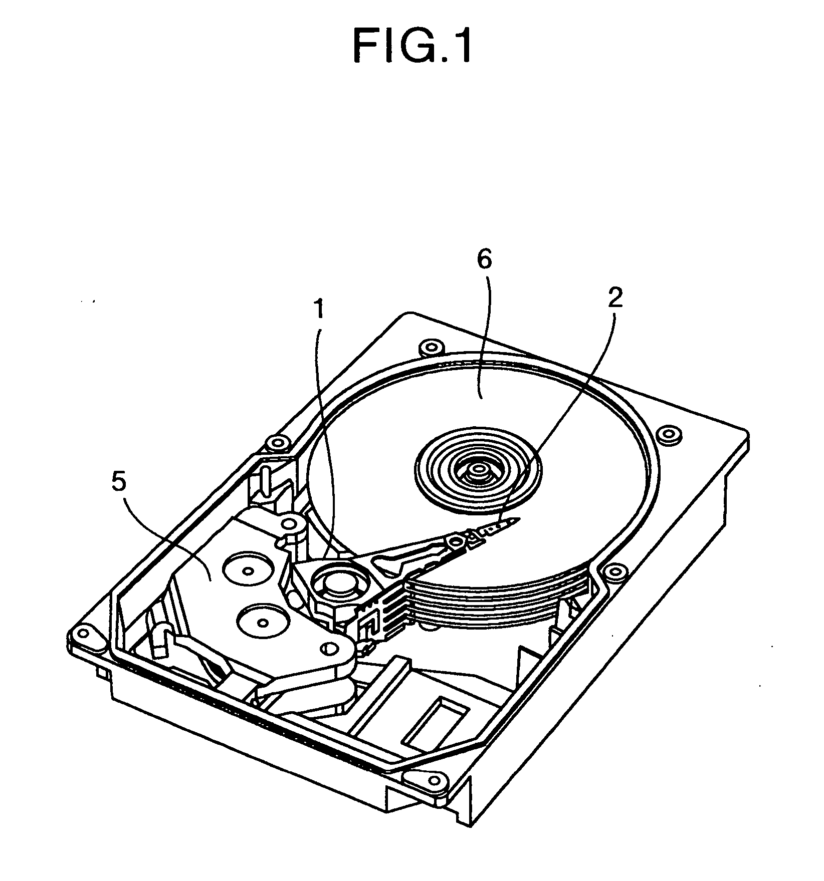
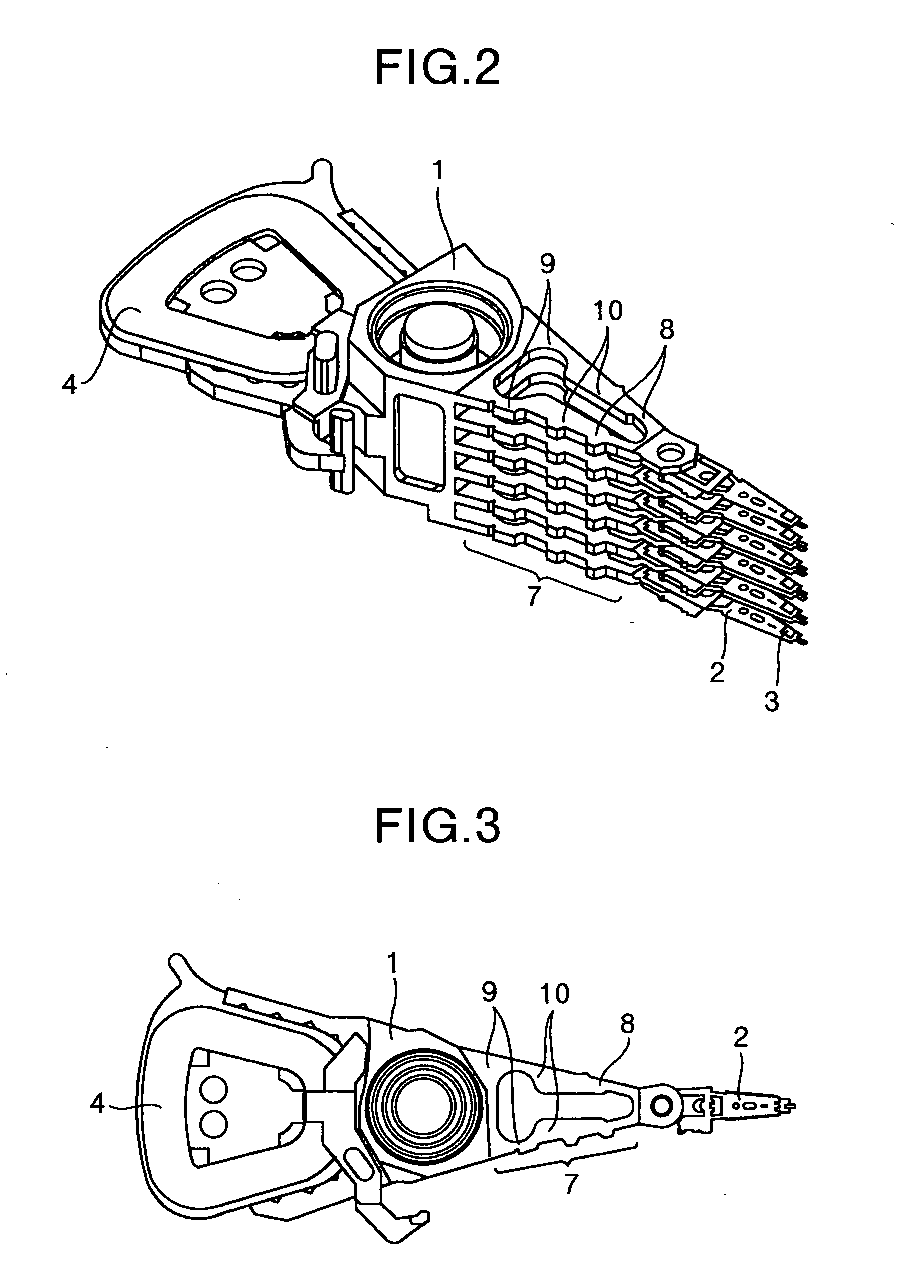
[0054] Referring to FIG. 1, FIG. 2 and FIG. 3, a slider 3 including a magnetic head (not shown) is mounted at the end of a carriage 1 via a suspension 2. When a current flows through a coil 4, a force is generated between a voice coil motor 5 and the coil 4, so that the carriage 1 rotates around a bearing section and thereby can position the slider 3 at an arbitrary radial position on a disk 6. The carriage 1 includes a carriage arm 7, and the carriage arm 7 has such a configuration in which the widths of the two arm members, corresponding to a front end area 8 and a back end area 9, are smaller than the width of a central (intermediate) area 10.
[0055]FIG. 4 and FIG. 5 illustrate principles of operation of the present invention. In the examples in FIG. 1 to FIG. 3, since the widths of the front end area 8 of the arm member and the back end area 9 of the arm member of the carriage arm 7 are smaller than the width of the central area 10 of the arm member, the present invention can be...
embodiment 2
[0058]FIG. 9 is a top view of a carriage arm assembly according to a second embodiment of the present invention. In the embodiment in FIG. 1 to FIG. 3, the widths of the front end area 8 of the arm member and the back end area 9 of the arm member of the carriage arm 7 are smaller than the width of the central area 10 of the arm member. On the other hand, in the embodiment in FIG. 9, the width of each arm member of the entire carriage arm 7 is reduced. This makes it possible to reduce the weight of the carriage arm, thus reduce inertial moment of the entire carriage arm assembly, which allows the time required for an access operation to be shortened. FIG. 10 shows a drawing of principles of operation. In the case of FIG. 10, the width of the entire carriage arm 7 is small, and therefore the carriage arm assembly can be modeled as elastic beams 13 instead of the rigid link mechanism as shown in FIG. 4. FIG. 11 shows a case where the carriage arm 7 is deformed. As with the case of FIG....
embodiment 3
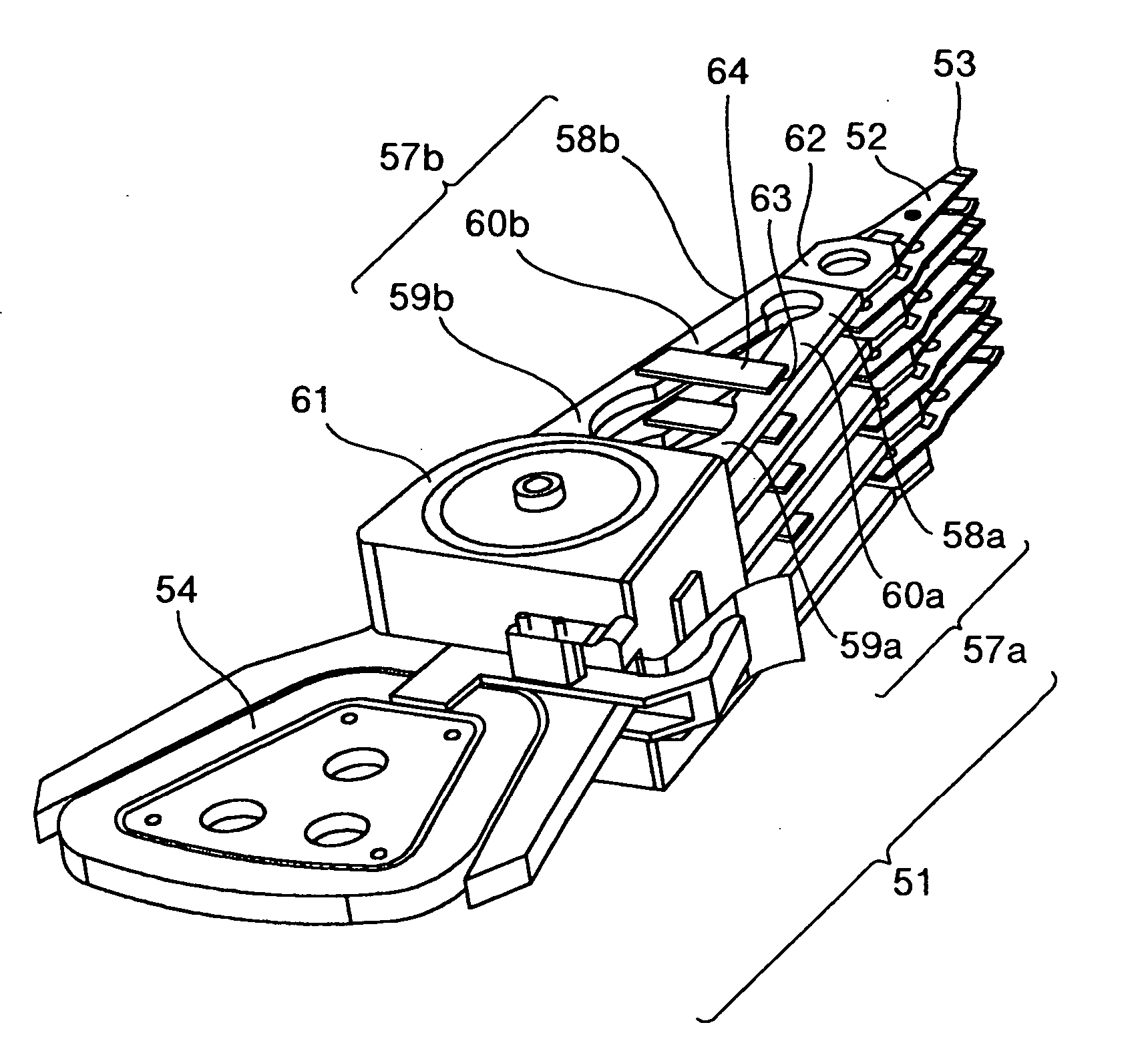
[0061]FIG. 14 is a perspective view of a carriage arm assembly according to a third embodiment of the present invention, and FIG. 15 is a top view of the carriage arm. FIG. 16 is a side view of the carriage arm. Furthermore, FIG. 17 shows an example of a magnetic disk apparatus incorporating the carriage arm assembly of the present invention. A slider 53 including a magnetic head (not shown) is mounted at the end of a carriage 51 via a suspension 52. When a current flows through a coil 54, a force is generated between a voice coil motor 55 and the coil 54, the carriage 51 rotates centered on the bearing section 61 around a rotation axis parallel to a rotation axis of the disk, and can thereby position the slider 53 at an arbitrary radial position (target track) on a disk 56.
[0062] The carriage 51 is the same as that of the first embodiment in which the carriage arm members 57a and 57b have a configuration such that the widths of the arm front end areas 58a and 58b and the arm back ...
PUM
| Property | Measurement | Unit |
|---|---|---|
| thick | aaaaa | aaaaa |
| thick | aaaaa | aaaaa |
| width | aaaaa | aaaaa |
Abstract
Description
Claims
Application Information
 - R&D
- Intellectual Property
- Life Sciences
- Materials
- Tech Scout
- Unparalleled Data Quality
- Higher Quality Content
- 60% Fewer Hallucinations
Browse by: Latest US Patents, China's latest patents, Technical Efficacy Thesaurus, Application Domain, Technology Topic, Popular Technical Reports.
© 2025 PatSnap. All rights reserved.Legal|Privacy policy|Modern Slavery Act Transparency Statement|Sitemap|About US| Contact US: help@patsnap.com


