Differential current-mode sensing methods and apparatuses for memories

a technology of current-mode sensing and memory, which is applied in the field of differential current-mode sensing methods and memory apparatuses, can solve the problems of reducing the differential voltage available for sensing

Inactive Publication Date: 2005-08-18
FUJITSU LTD
View PDF2 Cites 17 Cited by
  • Summary
  • Abstract
  • Description
  • Claims
  • Application Information

AI Technical Summary

Problems solved by technology

The inventors have recognized that this conventional approach is susceptible to the above-described sub-threshold currents

Method used


Image

  • Differential current-mode sensing methods and apparatuses for memories
  • Differential current-mode sensing methods and apparatuses for memories
  • Differential current-mode sensing methods and apparatuses for memories

Examples


Embodiment Construction

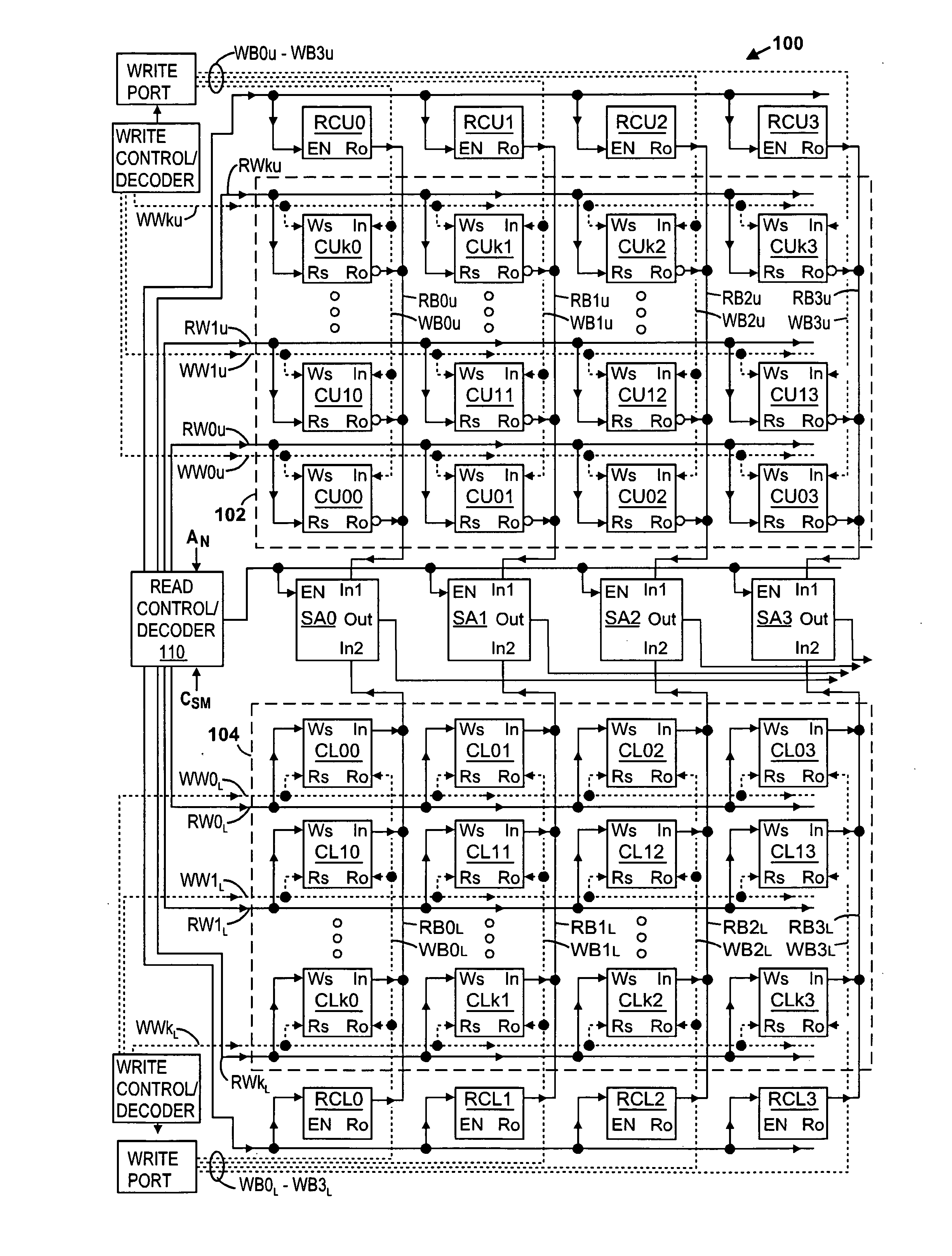
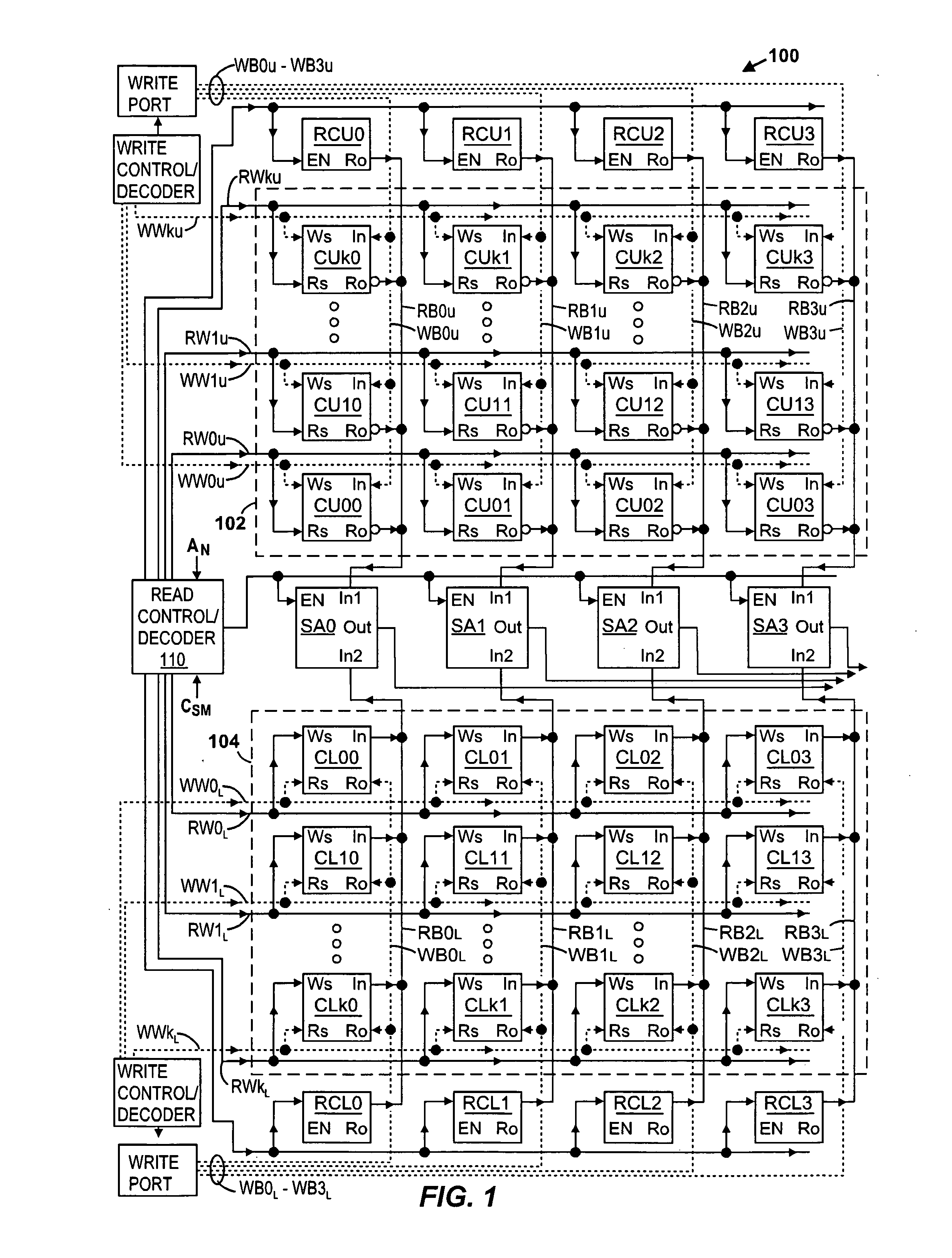
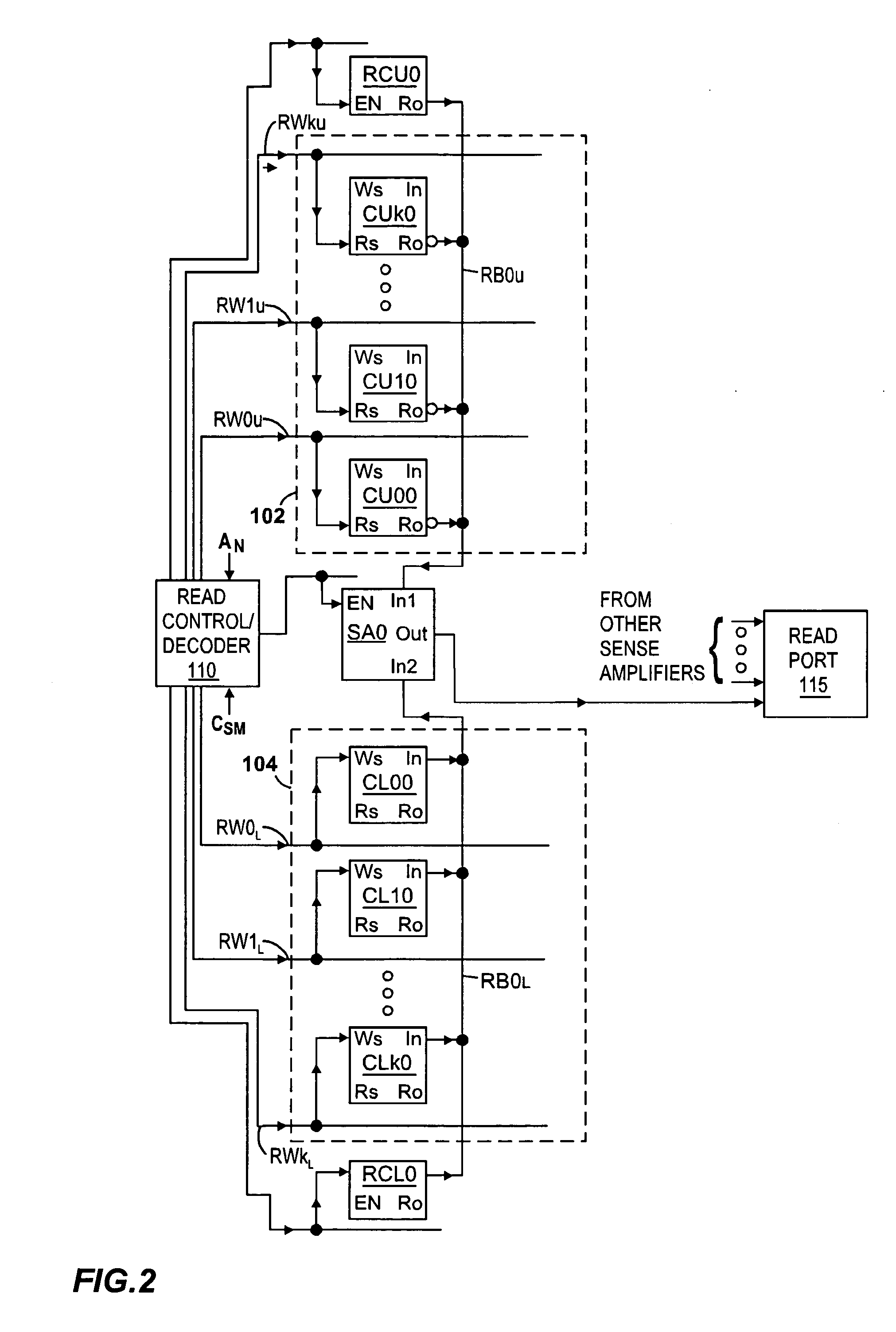
[0023]FIGS. 1-5 illustrate an exemplary memory 100 according to the present invention. (Crossing signal lines shown in the figures are not electrically coupled unless there is a dot placed at their intersection.) Referring to FIG. 1, memory array comprises a plurality of memory cells divided into an upper array 102 and a lower array 104, preferably with equal amounts of memory cells per array. The memory cells are arranged in rows and columns, with the first four columns being shown in FIG. 1 (and later identified with numbers 0-3). Each of the arrays 102 and 104 preferably has an equal number of columns, and equal numbers of rows are assigned to each of the arrays. The memory cells of upper array 102 are identified with reference numbers CU00-CUk3, where the first two letters “CU” represent cells of the upper array, where the first number (e.g., 0, 1, . . . , k) represents the row number in the upper array, and where the last number represents the column number (e.g., 0, 1, 2, or 3...


PUM


Abstract

Disclosed is a memory architecture where current sense amplifiers are used instead of voltage sense amplifiers, and where the memory cells normally disposed along a single bit line are divided between two half bit lines. Each half bit line is coupled to a respective input of the current sense amplifier. When one of the memory cells is selected for reading, it couples a current related to its stored data state to the half bit line that it is coupled to. During this operation, a reference current is generated on the other half bit line. Also disclosed are novel current sense amplifiers.

Description

FIELD OF THE INVENTION [0001] The present invention relates to methods and apparatuses for sensing the state of digital data stored in electronic memories. BACKGROUND OF THE INVENTION [0002] The semiconductor transistors used to construct electronic memory devices are becoming progressively smaller, with the minimum channel width and channel lengths of the devices decreasing in value. This progression allows memory devices to become smaller, but the smaller channel lengths of the transistors have created more sub-threshold leakage current in the devices, particularly in CMOS devices. As is known in the art, sub-threshold current is the amount of current that leaks through the channel of the device, from source terminal to drain terminal along the channel length, when the transistor is placed in the “OFF” state (VGS<Vt, the threshold voltage). Because of certain three-dimensional effects in the device, notably the fringing of electric fields in the device during sub-threshold cond...

Claims


Application Information

Patent Timeline
IPC IPC(8): G11C5/00G11C11/419G11C7/06G11C11/41G11C11/412G11C11/413
CPCG11C7/062G11C11/413G11C11/412
Inventor TZARTZANIS, NESTORWALKER, WILLIAM W.
Owner FUJITSU LTD
Why Eureka
Try Eureka