Method and apparatus for down conversion of radio frequency (rf) signals

a radio frequency and signal technology, applied in the field of methods and apparatus for down conversion of radio frequency (rf) signals, can solve the problems of high cost of use in more sophisticated modern applications, poor performance, and inability to isolate from digital nois

Active Publication Date: 2005-08-18
ICERA CANADA ULC
View PDF4 Cites 21 Cited by
  • Summary
  • Abstract
  • Description
  • Claims
  • Application Information

AI Technical Summary

Benefits of technology

Other advantages of the invention will also become clear from the other embodiments of the invention described hereinafter.

Problems solved by technology

As will be explained, these limitations make its use in more sophisticated modern applications expensive, and its performance poor.
The main problems with the super-heterodyne design are: it requires expensive off-chip components, particularly band pass filters 18, 24, 28, and low pass filter 38; the off-chip components require design trade-offs that increase power consumption and reduce system gain; image rejection is limited by the off-chip components, not by the target integration technology; isolation from digital noise can be a problem; and it is not fully integratable.
If the LO signal of a direct conversion receiver leaks into the signal path, it will also be demodulated to baseband along with the input signal, causing interference.
This LO leakage problem limits the utility of direct-conversion transceivers.
One of the current problems in the art is to develop effective receivers that can adapt to the varying requirements caused either by changing reception conditions, or even changing standards during the use of the device.
This has proven especially challenging as the frequencies of interest in the wireless telecommunications industry (especially low-power cellular / micro-cellular voice / data personal communications systems) have risen above those used previously (approximately 900 MHz) into the spectrum above 1 GHz.
Attempts to provide flexible designs in Radio Frequency Integrated Circuits (RFICs)—also known as monolithic microwave integrated circuits (MMICs)—allowing for multiple standards and varying conditions of reception have met with limited success.
This is an expensive and physically bulky approach which suffers from all of the performance problems described above.

Method used


Image

  • Method and apparatus for down conversion of radio frequency (rf) signals
  • Method and apparatus for down conversion of radio frequency (rf) signals
  • Method and apparatus for down conversion of radio frequency (rf) signals

Examples


Embodiment Construction

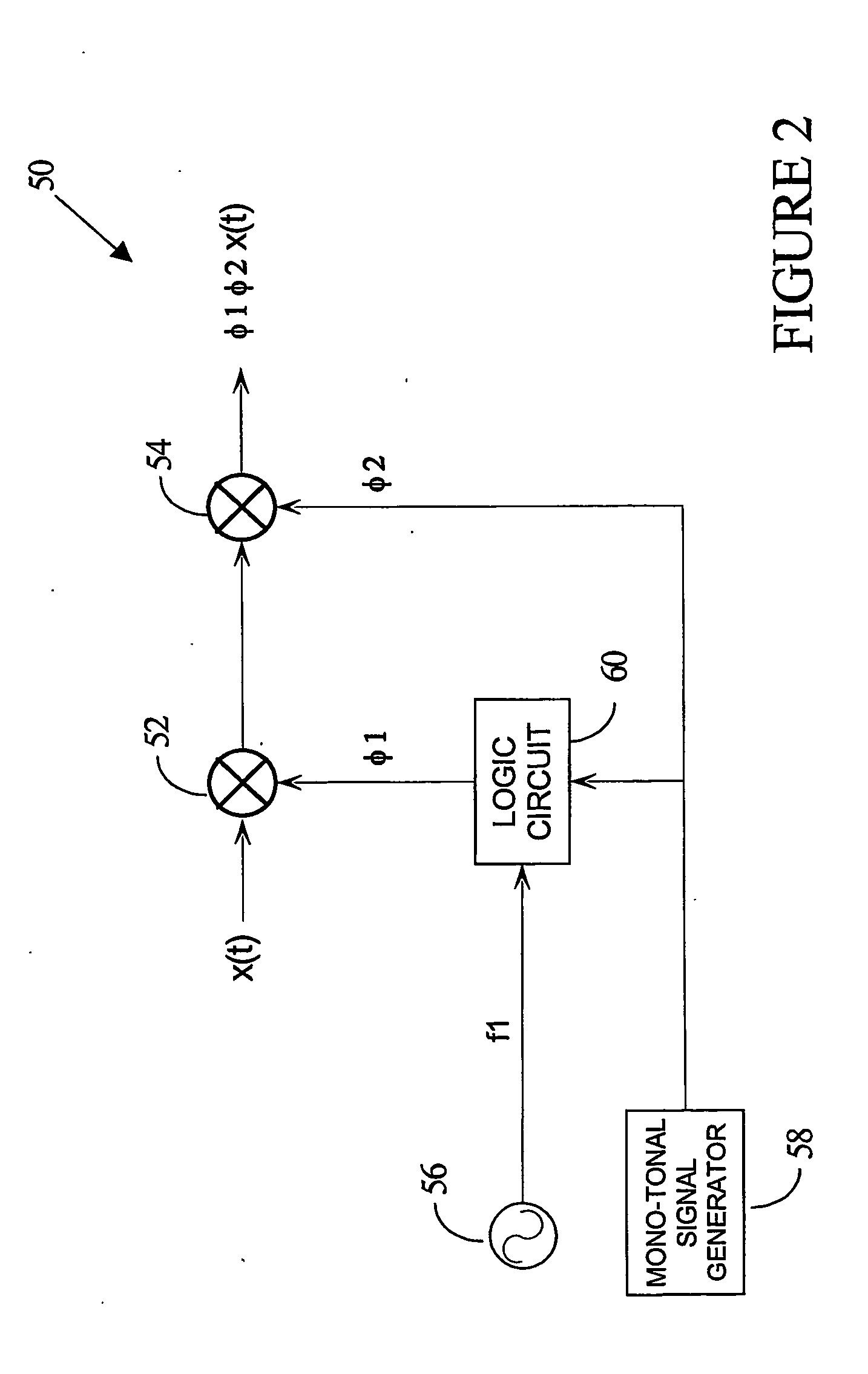
[0042] A circuit which addresses a number of the objects outlined above is presented as a block diagram in FIG. 2. This figure presents a demodulator topology 50 in which an input signal x(t) is down-converted by mixing it with two mixing signals φ1 and β2. As will be described, these two mixing signals are φ1 and φ2 are very different from mixing signals used in normal two-step conversion topologies (such as superheterodyne topologies). The main difference from the direct-conversion approach is that two mixing signals of the invention are used emulate the single mixing signal, and they do this without the usual short comings of direct-conversion, such as self-mixing.

[0043] As shown in FIG. 2, the input signal x(t) is mixed with a multi-tonal mixing signal φ1 using a first mixer 52 (multi-tonal, or non-mono-tonal, refers to a signal having more than one fundamental frequency tone. Mono-tonal signals have one fundamental frequency tone and may have other tones that are harmonically ...


PUM


Abstract

There is a need for an inexpensive, high-performance, fully-integrable, multi-standard transceiver, which suppresses spurious noise signals. The invention provides a topology that satisfies this need, using a first signal generator which produces an oscillator signal f1 and a second signal generator which produces a mono-tonal mixing signal φ2, where f1 is a multiple of the frequency of φ2; and a logic circuit for generating a multi-tonal mixing signal φ1, where φ1*φ2 has significant powerat the frequency of said local oscillator signal being emulated, neither of said cp1 nor said φ2 having significant power at the carrier frequency of said input signal x(t) or said LO signal being emulated.

Description

[0001] The present invention relates generally to communications, and more specifically to a method and apparatus of demodulating RF (radio frequency) signals. The preferred embodiment of the invention satisfies the need for an inexpensive, high-performance, fully-integrable, multi-standard receiver. BACKGROUND OF THE INVENTION [0002] Many communication systems modulate electromagnetic signals from baseband to higher frequencies for transmission, and subsequently demodulate those high frequencies back to their original frequency band when they reach the receiver. The original (or baseband) signal may be, for example: data, voice or video. These baseband signals may be produced by transducers such as microphones or video cameras, be computer generated, or transferred from an electronic storage device. In general, the high frequencies provide longer range and higher capacity channels than baseband signals, and because high frequency signals can effectively propagate through the air, t...

Claims


Application Information

Patent Timeline
Patent Type & Authority Applications(United States)
IPC IPC(8): H03D3/00H03D7/16H04B1/04H04B1/28H04B1/30
CPCH03D3/008H03D7/163H04B2001/0491H04B1/28H04B1/30H03D7/166H04B1/40
Inventor MANKU, TAJINDER
Owner ICERA CANADA ULC
Why Eureka
Try Eureka