
Industrial fabrics

a technology of industrial fabrics and fabrics, applied in the field of industrial fabrics, can solve the problems of rewetting of paper sheets, fiber shedding and wear of industrial fabrics, etc., and achieve the effects of improving smoothness and wear resistance, improving resistance to rewetting, and improving resistance to fiber shedding

Inactive Publication Date: 2005-08-18
VOTH FABRICS PATENT GMBH
View PDF17 Cites 29 Cited by
  • Summary
  • Abstract
  • Description
  • Claims
  • Application Information

AI Technical Summary

Benefits of technology

[0018] It is an object of the present invention to provide an industrial fabric which has improved resistance to rewet, and improved smoothness and wear resistance. It is a further object to provide an industrial fabric which has improved resistance to fiber shedding, superior macro and micro scale pressure uniformity, and is more economical to apply and process more consistently.
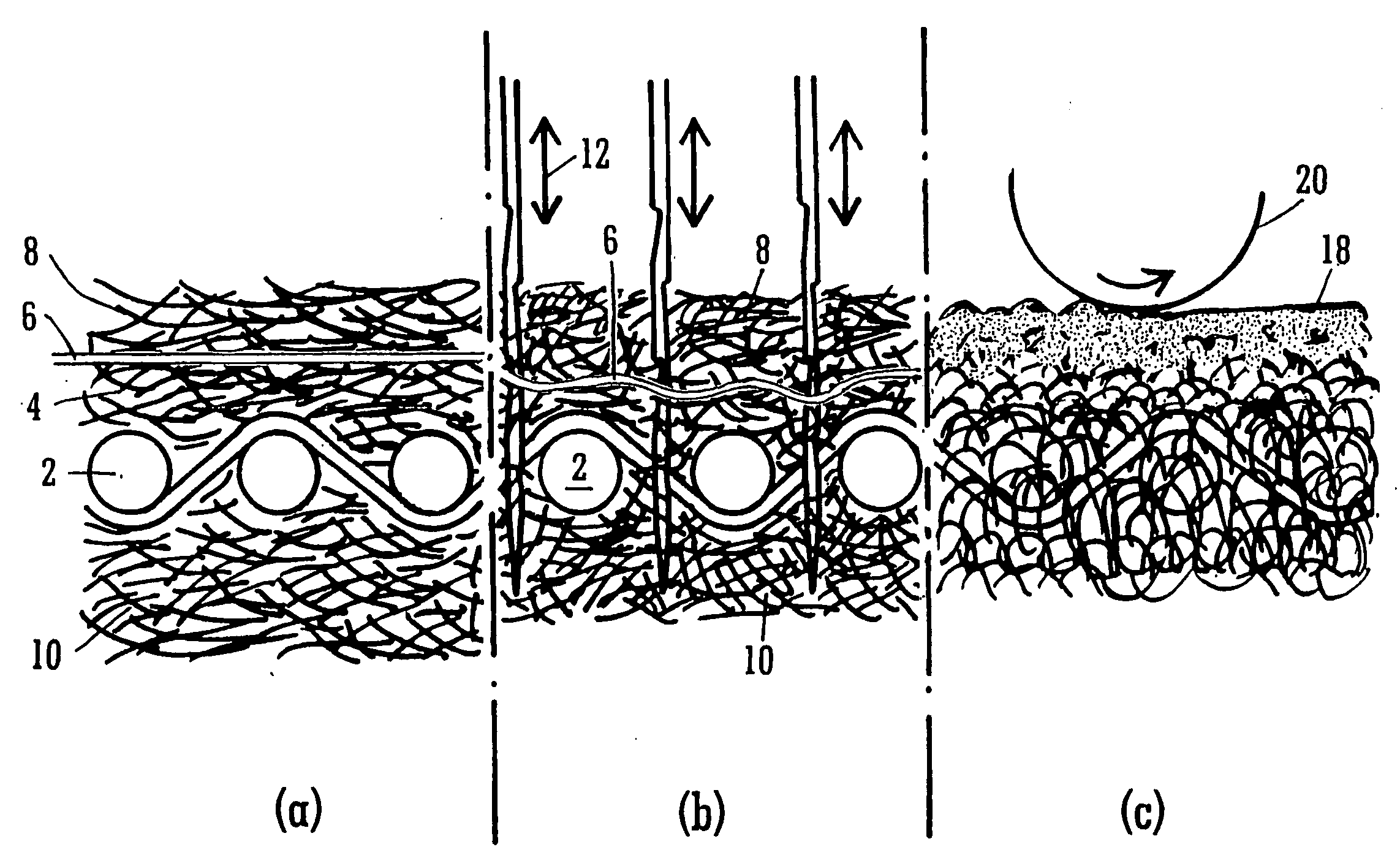
[0020] Needling results in perforation of the polymeric film layer enabling anchoring of the batt fibers therethrough. The subsequent thermoforming of that layer leads to at least partial encapsulation of the surrounding batt fibers and cross-over points thereof. This gives improved locking of the fibers of the batt together, thereby reducing shedding. Furthermore, the combination of the batt fibers and polymeric film provide a resistance to re-wet and hence superior sheet dryness when the fabric is used for paper machine clothing. It also blocks the backflow of filtered substances in other applications. In comparison to the papermaking fabric described in U.S. Pat. No. 5,372,876, the present fabric, when used as a papermaking fabric, has been found to provide a fabric with superior fiber bonding and wear resistance, with enhanced surface / pressure uniformity and contact area for improved sheet smoothness. It is intended that the term “thermoforming” not only covers fully melting the plastics layer, but also the supplying of enough thermal energy to soften, that is deform, that layer sufficiently to enable at least partial encapsulation of the batt fibers. The polymeric film layer may be provided under at least one layer of batt and / or on at least one layer of batt.
[0021] In another embodiment the polymeric film layer is beneath a fine, uniform, fibrous diffusion layer, which forms a surface layer. This has the advantage that once needled and thermoformed, the polymeric partially encapsulates and anchors the surface fibers, providing a reduction in shedding in this region and also an improved surface wear resistance.
[0022] For hot end use applications, a polymeric film material with a higher melting point may be used, for example, a material such as an ether based polyurethane. This has the advantage of minimal degradation, thereby maintaining bonding and fiber adhesion in the structure. The permeability of the fabric can be controlled by varying the thickness and quantity of polymeric film layers used, as well as by adjusting the needling procedure, that is the number of punches per unit area, and the amount and coarseness of the batt driven through. The heat setting conditions, which may include the use of compression from a calender can also be used to adjust the permeability of the fabric to the required level, by altering the degree of tension / compressive forces present during high temperature applications.
[0024] Preferably at least two batt layers are provided with the polymeric film layer being located under at least one of the batt layers. The polymeric film layer may be an elastomeric, thermoplastic polyurethane film. The film layer may have a thickness in the region of 0.05 mm. Polyurethane has the advantage that it has a lower melting point than that of the nylon fibers usually used to form the various batt layers, whilst still having a melting point which is above 100° C. thereby enabling continuous service of the fabric at relatively high temperatures without melting the polyurethane during use. Furthermore, being an elastomer, polyurethane maintains its original properties even after repeated melt / cool process cycles and it's high melt viscosity prevents it from “flowing” excessively at high temperatures.

Problems solved by technology

When in use, industrial fabrics suffer from the problems of fiber shedding and wear.
Also, rewetting of a paper sheet, upon exit of the sheet from the press-nip of the papermaking machine, is a recognized problem.

Method used


Image

  • Industrial fabrics
  • Industrial fabrics
  • Industrial fabrics

Examples


Embodiment Construction

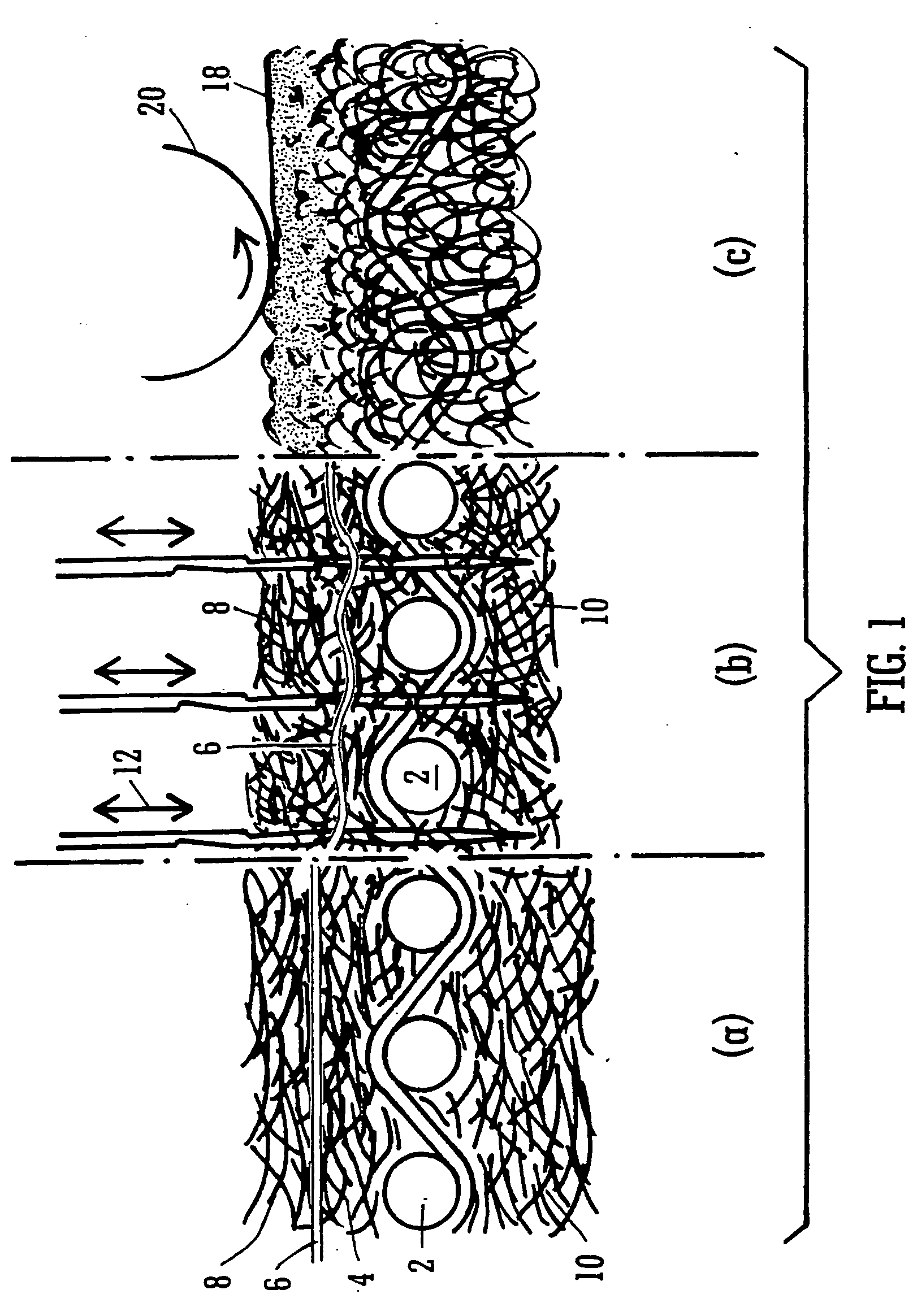
[0034] Referring now to the drawings and more particularly to FIG. 1(a), an industrial fabric constructed in accordance with an embodiment of the present invention includes a base layer 2, a first upper batt layer 4, a fine 0.051 mm (0.002 inch) thick elastomeric, a thermoplastic polyurethane film layer 6, an uppermost batt layer 8, and a lower batt layer 10. Polyurethane film layer 6 has a lower melting point than the other layers. These layers are joined, as best illustrated in FIG. 1(b), by needling 12 the layers together. Needling causes the individual fibers of the batt layers to intermingle and to link through base layer 2 to lock the layers together. Furthermore, the needling action perforates polyurethane film 6 to give a more open structure, through which the batt fiber is driven. As best illustrated in FIG. 1(c), the upper paper contacting surface of fabric 18 is heated at 200° C. using cylinder 20, this heat is sufficient to melt the lower melting point needled polyuretha...


PUM

PropertyMeasurementUnit
Thicknessaaaaaaaaaa
Melting pointaaaaaaaaaa
Elastomericaaaaaaaaaa

Abstract

An industrial fabric including a base layer, a batt layer and at least one low-melt polymeric film layer, which has been needled into the batt layer and subsequently thermoformed to at least partially encapsulate the fibers of the batt layer.

Description

CROSS REFERENCE TO RELATED APPLICATIONS [0001] This is a continuation of PCT application No. PCT / EP03 / 02375, entitled “INDUSTRIAL FABRICS”, filed Mar. 7, 2003.BACKGROUND OF THE INVENTION [0002] 1. Field of the Invention [0003] The present invention relates to industrial fabrics for use in phase separation applications such as media for filtration and fabrics for papermaking. [0004] 2. Description of the Related Art [0005] When in use, industrial fabrics suffer from the problems of fiber shedding and wear. Also, rewetting of a paper sheet, upon exit of the sheet from the press-nip of the papermaking machine, is a recognized problem. Various methods of alleviating these drawbacks have been proposed. [0006] In the papermaking felt described in U.S. Pat. No. 5,372,876 (Appleton Mills), at least one hydrophobic layer of co-joined synthetic, such as nylon filaments, is disposed between a base fabric and the batt material and / or between at least two batt layers. The various layers are join...

Claims


Application Information

Patent Timeline
IPC IPC(8): B32B27/12D21F7/08
CPCB32B27/12D21F7/086D21F7/083Y10T442/3724Y10T442/682Y10T442/674Y10T442/3707Y10T442/3854B32B5/06B32B2307/73B32B27/40
Inventor CROOK, ROBERT L.ALDRICH, WILLIAM DANIELPATEL, SANJAY
Owner VOTH FABRICS PATENT GMBH
Learn More