Lesion identification system for surgical operation and related method

a technology for identifying systems and lesions, applied in the field of lesion identification systems for surgical operations, can solve the problems of increased labor hours, difficult to take a proper response to an observation image of the tube with the magnet for the organism, and dissemination to occur

Inactive Publication Date: 2005-08-18
OLYMPUS CORP
View PDF32 Cites 39 Cited by
  • Summary
  • Abstract
  • Description
  • Claims
  • Application Information

AI Technical Summary

Benefits of technology

[0020] The present invention has an object to identify a location of

Problems solved by technology

However, since there is a probability for the surgery marker to be inserted to the lesion by penetrating through a normal site on a transcutaneous fashion, lesion cells scatter, resulting in dissemination to occur.
However, when executing endoscopic treatment to the organism, the tube with the magnet for the organism is hard to take a proper response to an observation image of an endoscope even if the location of the magnet is detected.
However, in such a case, a need arises for a flexiblescope, unnecessary for surgical operation per se, to be prepared only for the confirmation of the location of the lesion (operation site) and, in addition, it is required to keep an operator who has an ability to manipulate the flexiblescope.
For this reason, using the endoscope just for the positional confirmation to be executed during surgical treatment is disadvantageous because of an increase in labor hours, such as preparation and clearing off of the instrument, cumbersome and complicated techniques, keeping of the operator and increased costs.
However, this clip is used for visual observation and it is sometime hard to view the light emitted from the clip, providing a difficulty in usage.
However, in such a case, since the X-ray fluoroscope is used for confirming the location of the lesion, issues arise for the patient to be exposed to radioactivity.
Also, the X-ray transparent image is completely different from the observation image obtained by the laparoscope, resulting in a difficulty in identifying the location of the lesion in relationship between the X-ray transparent imag

Method used


Image

  • Lesion identification system for surgical operation and related method
  • Lesion identification system for surgical operation and related method
  • Lesion identification system for surgical operation and related method

Examples


first embodiment

[0076] (First Embodiment)

[0077] First, a first embodiment is described with reference to FIGS. 1 to 9.

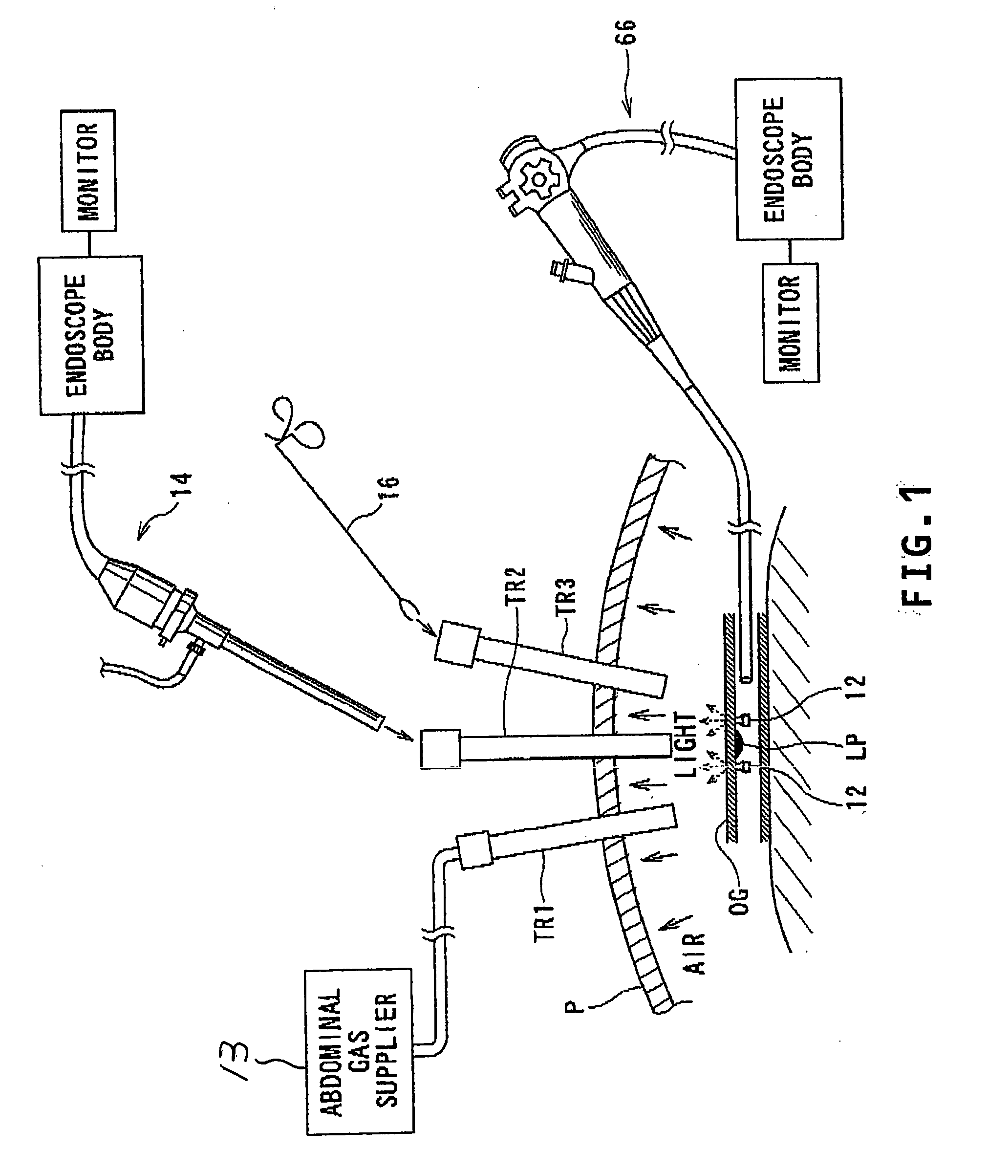
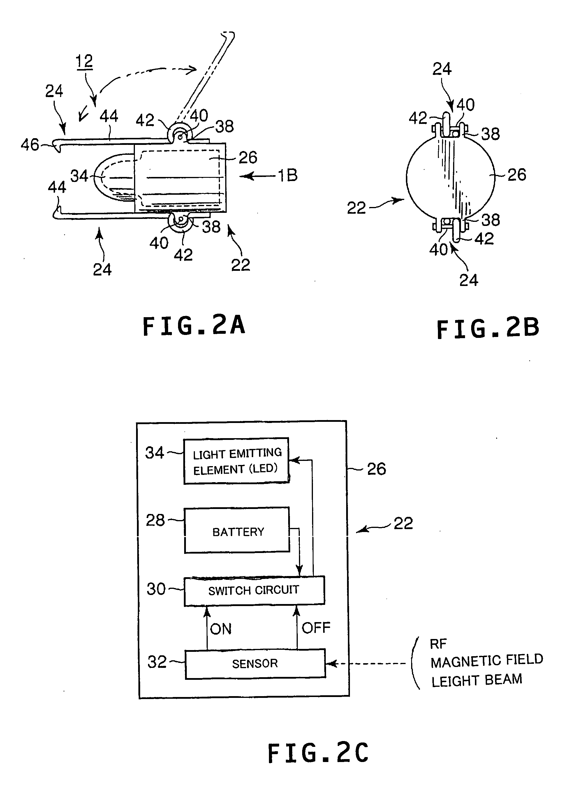
[0078] As shown in FIG. 1, a lesion identification system for surgical operation of the presently filed embodiment is comprised of light source clips 12 (see FIG. 2A) each serving as a light marker (marker) having a light emitting function and a clipping function, an endoscope (first endoscope device) 66 (see FIG. 7A) serving as a soft scope for use in indwelling the light source clips 12, which will be described later, in the vicinity of a lesion, and an endoscope (second endoscope device) 14 (see FIG. 3A), serving as a rigidscope for surgical operation, which detect lights emitted by the light source clips 12.

[0079] In FIG. 1, further, reference P designates a patient (organ); OG designates an organ of the patient P to be targeted; and LP designates a lesion of the organ OG. Also, trocars TR1 to TR3 are inserted to a site of the patient P to be treated during operations. Among t...

second embodiment

[0117] (Second Embodiment)

[0118] Next, a second embodiment is described with reference to FIGS. 10 and 11. This embodiment is a modified form of the first embodiment and the same component parts as those described in the first embodiment bear like reference numerals to omit detailed description. Hereunder, the way of such omission may similarly apply to third to ninth embodiments.

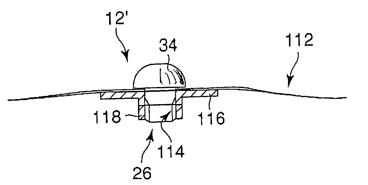
[0119] As shown in FIG. 10A, a light marker 12′ of a lesion identification system for surgical operation of the presently filed embodiment differs from the light source clip 12, serving as the light marker, of the first embodiment in shapes of the engagement members 24 and the receiver case 26. The receiver case 26 has the same internal structure as that of the first embodiment described above.

[0120] An LED 34 of the light marker 12′ is formed in a hemispheric shape. A center of the LED 34 and a center of the receiver case 24 are aligned on the same axis and a diameter of the LED 34 is formed in a larger ...

third embodiment

[0128] (Third Embodiment)

[0129] Now, reference is made to FIGS. 12 to 15 to describe a third embodiment.

[0130] As shown in FIG. 12A, a loop-shaped light marker 130 is employed in place of the light markers (light source clips 12) described with reference to the first embodiment. The loop-shaped light marker 130 is comprised of a tubular holder 32, a light source 22 mounted inside the holder 132, and a light guide 134 through which a light emitted from the light source 22 is guided to an outside of the holder 132.

[0131] The light guide 134 is comprised of a tubular light guide base 136 that is retained by caulking a distal end of the holder 132, and a light guide 138 having both ends disposed in an inner aperture of the base 136 and mounted to the same to allow the light guide 138 to extend from the base 136 in a loop shape to serve as a loop-shaped light source. That is, the base 136 has a distal end that is fixedly secured to the holder 132 by means of a first caulked portion 140...


PUM


Abstract

A lesion identification system for surgical operations has a light marker adapted for placement in the vicinity of a lesion inside an organ of an organism, and a location-identifying device detecting a light emitted from the light marker at an outside of the organ for identifying a location of the lesion. The marker includes a light emitter and an engagement member associated with the emitter to be engageable with a wall of the organ. The engagement member includes a clip. The light emitter emits light with a wavelength in a near-infrared range. The device includes an endoscope comprising an inserter section having an image pickup element picking up a reflected light, involving the light from the light marker, at an outside of the organ, and an image pickup unit allowing the reflected light, picked by the image pickup element, to be generated as an image for display on a monitor.

Description

CROSS REFERENCE TO RELATED APPLICATIONS [0001] The present application relates to and incorporates by reference Japanese Patent Application No. 2004-030509 filed on Feb. 6, 2004. BACKGROUND OF THE INVENTION [0002] 1. Technical Field [0003] The present invention relates to a lesion identification system for surgical operation for identifying a marker indicative of a location of a lesion of an organism. [0004] 2. Related Art [0005] In modern surgical operations, various attempts have heretofore been undertaken to provide techniques known in the art to assist operations using a marker, placed prior to executing the operations and indicative of a location of a lesion in an internal site of a patient, as a field mark. As for these techniques, various techniques have been proposed in the related art. [0006] For instance, Japanese Patent Publication No. 2794162 discloses an operation marker. The operation marker is comprised of a marker needle that has one end to which a lead wire is fixed...

Claims


Application Information

Patent Timeline
IPC IPC(8): A61B1/00A61B1/06A61B5/06A61B5/07A61B19/00
CPCA61B5/06A61B19/5202A61B19/54A61B2019/545A61B2019/5433A61B2019/5441A61B2019/5445A61B2019/5408A61B2090/3945A61B90/30A61B90/39A61B2090/3908A61B2090/3933A61B2090/3941A61B2090/395
Inventor KAJI, KUNIHIDEHATTA, SHINJISUZUKI, KEITAMORIZANE, YUICHITAKARA, TOSHIYUKESAITO, TATSUYATAKIGAWA, TAKESHI
Owner OLYMPUS CORP
Why Eureka
Try Eureka